132
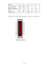
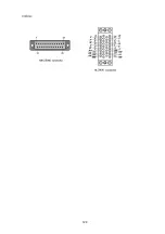
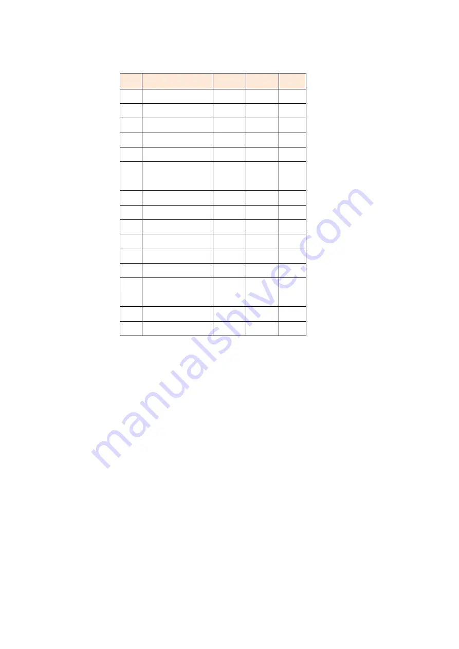
The pin out of DB-15 connector on X.25 adaptor cable:
Pin Signal
Abbr
.
DTE
DC
E
1
Shield
--
--
--
2
Transmit (A)
TA
Out
In
3
Control (A)
CA
Out
In
4
Receive (A)
RA
In
Out
5
Indication (A) IA
In
Out
6
Signal Timing
(A)
SA
In
Out
7
Unassigned
8
Ground
--
--
--
9
Transmit (B)
TB
Out
In
10
Control (B)
CB
Out
In
11
Receive (B)
RB
In
Out
12
Indication (B)
IB
In
Out
13
Signal Timing
(B)
SB
In
Out
14
Unassigned
15
Unassigned
Functional Description:
The Signal Element Timing (clock)
(S)
is provided by the DCE. This means
that the NTU is output the correct clocking and that X.21 is a
synchronous interface. Hardware handshaking is done by the Control
(C)
and Indication
( I )
lines. The Control is used by the DTE and the
Indication is the DCE one.
Summary of Contents for SHRM03b TDM Series
Page 1: ...SHRM03b G SHDSL bis TDM Series 4U 19 Chassis ...
Page 2: ......
Page 23: ...23 When using 4 wire 2 pairs mode only the upper side of RJ 45 connector can be used ...
Page 37: ...37 3 5 1 Menu Tree diagram 2 wire mode ...
Page 38: ...38 3 5 2 Menu Tree diagram 4 wire mode ...
Page 52: ...52 75 Ohms 120 Ohms BNC Connector RJ 45 Connector ...
Page 59: ...59 ...
Page 78: ...78 ...
Page 82: ...82 3 8 2 4 Series interface 4 wire mode 3 8 2 5 Ethernet interface 2 wire mode ...
Page 83: ...83 3 8 2 6 Ethernet interface 4 wire mode ...
Page 84: ...84 3 8 2 7 T1 interface 2 wire mode 3 8 2 8 T1 interface 4 wire mode ...
Page 86: ...86 3 8 3 3 Ethernet interface For Ethernet interface model ...
Page 87: ...87 3 8 3 4 T1 interface For T1 interface model ...
Page 105: ...105 Ethernet Rate Auto Speed Duplex ...
Page 113: ...113 side Click Reset button and the values will be set to default ...
Page 116: ...116 4 5 7 4 SNMP All SNMP parameter must setup on this item ...
Page 128: ...128 cable ...
Page 131: ...131 ...
Page 136: ...136 ...
Page 137: ......
Page 138: ......

