26
2 Installation
2.1
General
The Installation chapter will cover the physical installation of the SHRM03b
series, the electrical connections, line card installation and cabling
requirements. A brief overview of the functional components such as power
modules, line cards and management options will also be outlined in this
chapter.
Required Tools
You will need these tools to install the SHRM03b series Rack Mount:
• Phillips screw driver for chassis installation screws.
• Wrist strap or other personal grounding device to prevent ESD occurrences.
• Antistatic mat or antistatic foam to set the equipment on.
2.2
Unpacking
Step 1. Inspect the outside carton for any shipping damage and report
immediately to your freight forwarder if any damage is visible.
Step 2. Place the shipping carton with the top facing up. Carefully cut through
the shipping tape with a box cutter knife.
Step 3. Open the top cover of the carton and remove any pizza box.
Step 4. Pull the entire chassis straight up out of the carton
Step 5. The chassis should be wrapped in a plastic bag. Remove the chassis
from the plastic bag. Set the chassis on a secure flat surface and again inspect
for any shipping damage. Report any damage immediately to your freight
forwarder.
2.3
Installation with Rack
The rack mount brackets that ship with the SHRM03b series chassis allow
mounting in either 19" or 23" wide rack spaces. A total of four different
mounting configurations are possible. Please see the chassis top view graphics
below.
Summary of Contents for SHRM03b TDM Series
Page 1: ...SHRM03b G SHDSL bis TDM Series 4U 19 Chassis ...
Page 2: ......
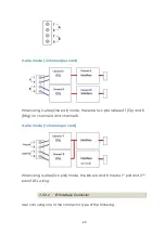
Page 23: ...23 When using 4 wire 2 pairs mode only the upper side of RJ 45 connector can be used ...
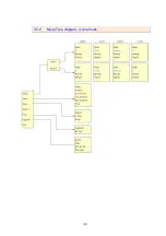
Page 37: ...37 3 5 1 Menu Tree diagram 2 wire mode ...
Page 38: ...38 3 5 2 Menu Tree diagram 4 wire mode ...
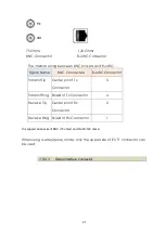
Page 52: ...52 75 Ohms 120 Ohms BNC Connector RJ 45 Connector ...
Page 59: ...59 ...
Page 78: ...78 ...
Page 82: ...82 3 8 2 4 Series interface 4 wire mode 3 8 2 5 Ethernet interface 2 wire mode ...
Page 83: ...83 3 8 2 6 Ethernet interface 4 wire mode ...
Page 84: ...84 3 8 2 7 T1 interface 2 wire mode 3 8 2 8 T1 interface 4 wire mode ...
Page 86: ...86 3 8 3 3 Ethernet interface For Ethernet interface model ...
Page 87: ...87 3 8 3 4 T1 interface For T1 interface model ...
Page 105: ...105 Ethernet Rate Auto Speed Duplex ...
Page 113: ...113 side Click Reset button and the values will be set to default ...
Page 116: ...116 4 5 7 4 SNMP All SNMP parameter must setup on this item ...
Page 128: ...128 cable ...
Page 131: ...131 ...
Page 136: ...136 ...
Page 137: ......
Page 138: ......

