27
2.3.1
Attaching the Mounting Brackets
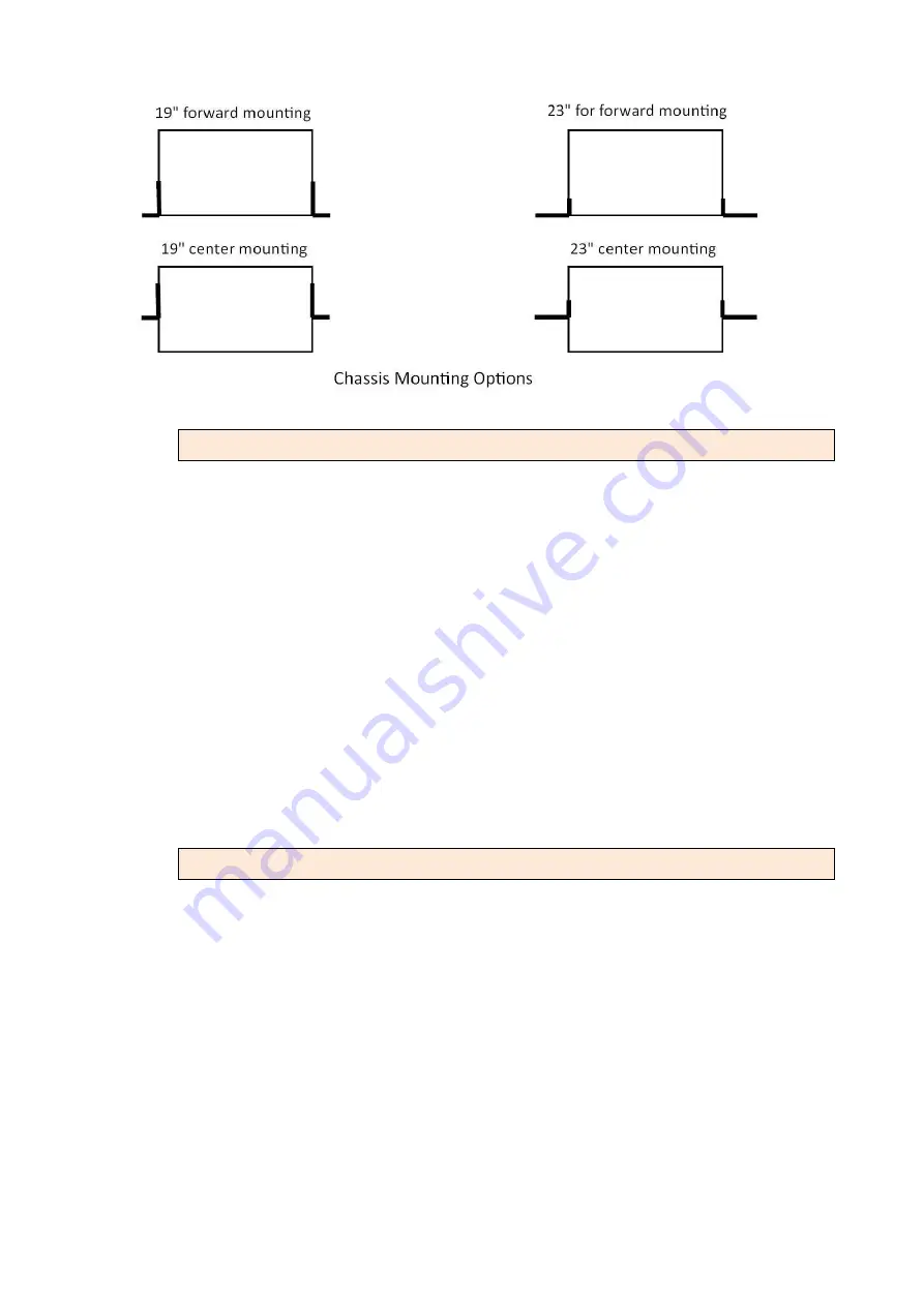
Step 1. Place the supplied rack- mounting bracket on one side of chassis
ensuring the mounting holes on the chassis line up to the mounting holes
on the rack mounting bracket.
Step 2. Insert the supplied screws (M3X4 flat head screws) into the rack
mounting holes and tighten with a screwdriver.
Precautions: Only M3X4 flat head screws can be used, failure to use the
proper screws may damage the unit.
Step 3. Repeat the process for the rack-mounting bracket on the other side of
the chassis.
Step 4. You may now mount the chassis on a rack. Proceed to the next
section.
2.3.2
Mounting the chassis on a Rack
Precautions:
(a)
Make sure the rack will safely support the combined weight of all the
equipment it contains.
(b)
Make sure the position of the chassis doesn’t make the rack unstable or
top-heavy. Take all necessary precautions to anchor the rack securely
before installing the unit.
(c)
For proper ventilation, ensure the air flow around the front, sides, and back
of the chassis is not restricted.
(d)
Do not install the chassis in an environment where the operation ambient
Summary of Contents for SHRM03b TDM Series
Page 1: ...SHRM03b G SHDSL bis TDM Series 4U 19 Chassis ...
Page 2: ......
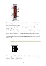
Page 23: ...23 When using 4 wire 2 pairs mode only the upper side of RJ 45 connector can be used ...
Page 37: ...37 3 5 1 Menu Tree diagram 2 wire mode ...
Page 38: ...38 3 5 2 Menu Tree diagram 4 wire mode ...
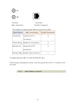
Page 52: ...52 75 Ohms 120 Ohms BNC Connector RJ 45 Connector ...
Page 59: ...59 ...
Page 78: ...78 ...
Page 82: ...82 3 8 2 4 Series interface 4 wire mode 3 8 2 5 Ethernet interface 2 wire mode ...
Page 83: ...83 3 8 2 6 Ethernet interface 4 wire mode ...
Page 84: ...84 3 8 2 7 T1 interface 2 wire mode 3 8 2 8 T1 interface 4 wire mode ...
Page 86: ...86 3 8 3 3 Ethernet interface For Ethernet interface model ...
Page 87: ...87 3 8 3 4 T1 interface For T1 interface model ...
Page 105: ...105 Ethernet Rate Auto Speed Duplex ...
Page 113: ...113 side Click Reset button and the values will be set to default ...
Page 116: ...116 4 5 7 4 SNMP All SNMP parameter must setup on this item ...
Page 128: ...128 cable ...
Page 131: ...131 ...
Page 136: ...136 ...
Page 137: ......
Page 138: ......


