29
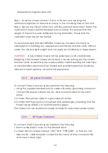
3. Connect the power cable to the DC power supply.
4. Confirm that the chassis is connected and operating by checking that the
Power Supply LED(DC) on the front panel is green.
WARNING:
Before connect the DC power cable to the input terminal block
of rear panel, ensure that the power switch in the “OFF” position and the DC
power is OFF.
NOTE:
A qualified electrician must perform all connections to DC power and
to safety grounds. All electrical wiring must comply with applicable local or
national codes and practices.
2.4
Line Card Removal / Replacement
This section will explain how to install and remove SHDSL.bis Line Cards.
2.4.1
Installing a Line Card
Use the following procedure to install a SHDSL.bis Line Card in the main chassis.
Step 1. Using either an anti-static grounded wrist strap or touching a grounded
metal frame, remove the line card from its anti-static protective bag by
grasping the metal panel. Do not touch the PCB or components on the PCB.
Step 2. While still grasping the center of the front panel of the card with one
hand, place the other hand under the card to support it.
Step 3. Slide the Line Card into the slot until it makes contact with the
backplane.
Step 4. Gently press the card the remaining way into the backplane
connector until fully seated.
Step 5. Tighten the two thumbscrews by hand.
2.4.2
Removing a Line Card
Use the following procedure to remove a SHDSL.bis Line Card from the main
chassis.
Step 1. Using either an anti-static ground wrist strap or by touching a grounded
metal frame, loosen the two thumbscrews, using a flat blade screwdriver if
necessary. Do not remove the screws completely.
Summary of Contents for SHRM03b TDM Series
Page 1: ...SHRM03b G SHDSL bis TDM Series 4U 19 Chassis ...
Page 2: ......
Page 23: ...23 When using 4 wire 2 pairs mode only the upper side of RJ 45 connector can be used ...
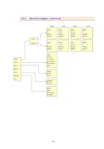
Page 37: ...37 3 5 1 Menu Tree diagram 2 wire mode ...
Page 38: ...38 3 5 2 Menu Tree diagram 4 wire mode ...
Page 52: ...52 75 Ohms 120 Ohms BNC Connector RJ 45 Connector ...
Page 59: ...59 ...
Page 78: ...78 ...
Page 82: ...82 3 8 2 4 Series interface 4 wire mode 3 8 2 5 Ethernet interface 2 wire mode ...
Page 83: ...83 3 8 2 6 Ethernet interface 4 wire mode ...
Page 84: ...84 3 8 2 7 T1 interface 2 wire mode 3 8 2 8 T1 interface 4 wire mode ...
Page 86: ...86 3 8 3 3 Ethernet interface For Ethernet interface model ...
Page 87: ...87 3 8 3 4 T1 interface For T1 interface model ...
Page 105: ...105 Ethernet Rate Auto Speed Duplex ...
Page 113: ...113 side Click Reset button and the values will be set to default ...
Page 116: ...116 4 5 7 4 SNMP All SNMP parameter must setup on this item ...
Page 128: ...128 cable ...
Page 131: ...131 ...
Page 136: ...136 ...
Page 137: ......
Page 138: ......

