51
that the signal can be effectively transmitted. This means,
however, that a long sequence of zeros in data stream will
cause problems, since the NTU receiving the signal relies on
the signal to recover the 2048kbps clock.
3.6.4.3
Ais
AIS or Alarm Indication Signal is a method to inform the remote connection
that there is a signal or sync problem with the E1. AIS is only valid in framed
mode E1, not in Unframed E1. The setting here of AIS enabled (on) or not (off)
and is for testing with AIS. When enabled, the E1 will transmit the AIS and it
should be confirmed at the remote device (AIS indication lit). After testing,
please turn AIS back off.
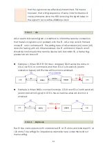
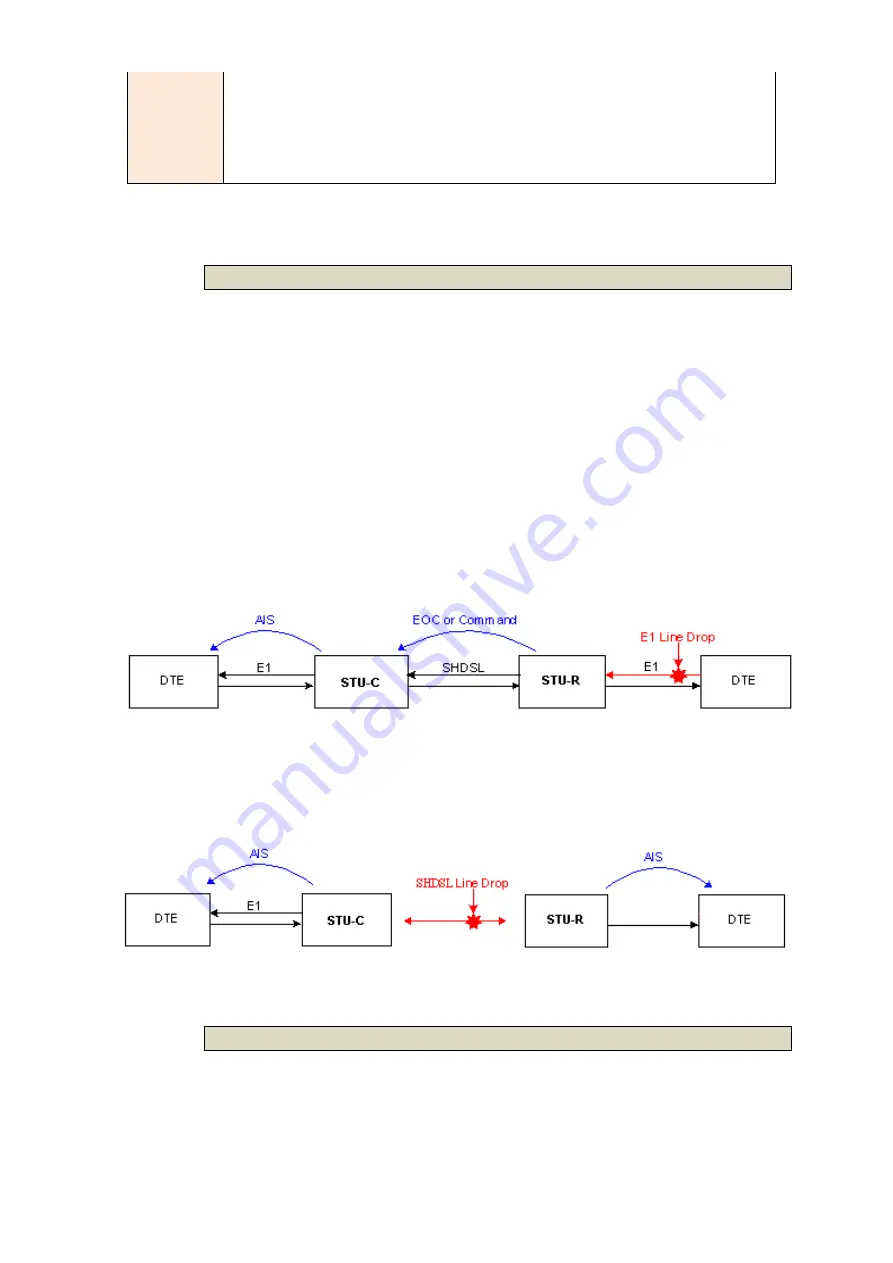
Example 1: When STU-R E1 RX line is dropped, STU-R sends the status to
STU-C via EOC or command, and then STU-C will send AIS (Alarm
Indication Signal) to DTE while AIS function is enabled.
Example 2: When SHDSL connection drops, STU-R and STU-C both send AIS
(Alarm Indication Signal) to DTE in the same time while AIS function is
enabled.
3.6.4.4
Build outs
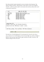
The E1 line card supports both unbalanced E1 at 75 ohms and balanced E1 at
120 ohms. The settings for impedance are made here under the build out
menu setting.
Summary of Contents for SHRM03b TDM Series
Page 1: ...SHRM03b G SHDSL bis TDM Series 4U 19 Chassis ...
Page 2: ......
Page 23: ...23 When using 4 wire 2 pairs mode only the upper side of RJ 45 connector can be used ...
Page 37: ...37 3 5 1 Menu Tree diagram 2 wire mode ...
Page 38: ...38 3 5 2 Menu Tree diagram 4 wire mode ...
Page 52: ...52 75 Ohms 120 Ohms BNC Connector RJ 45 Connector ...
Page 59: ...59 ...
Page 78: ...78 ...
Page 82: ...82 3 8 2 4 Series interface 4 wire mode 3 8 2 5 Ethernet interface 2 wire mode ...
Page 83: ...83 3 8 2 6 Ethernet interface 4 wire mode ...
Page 84: ...84 3 8 2 7 T1 interface 2 wire mode 3 8 2 8 T1 interface 4 wire mode ...
Page 86: ...86 3 8 3 3 Ethernet interface For Ethernet interface model ...
Page 87: ...87 3 8 3 4 T1 interface For T1 interface model ...
Page 105: ...105 Ethernet Rate Auto Speed Duplex ...
Page 113: ...113 side Click Reset button and the values will be set to default ...
Page 116: ...116 4 5 7 4 SNMP All SNMP parameter must setup on this item ...
Page 128: ...128 cable ...
Page 131: ...131 ...
Page 136: ...136 ...
Page 137: ......
Page 138: ......


