7
1 Introduction
This manual is used to explain the installation and operating procedures for the
SHRM03b series Rack Mount, G.SHDSL.bis TDM Based Line Cards (SHRM03b,
SHRM03b-E1, SHRM03b-V35, SHRM03b-ET100), NMS and present its capabilities
and specifications.
The manual is divided into 4 Chapters with Appendix.
The first three chapters are the Introduction, Installation and Operation of TDM
line card.
The last chapter is introduction and operation of NMS network management
card.
The Appendix includes the pin assignments of special cables.
1.1
General Description
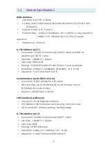
The SHRM03bB series is a 4U chassis that may be placed on a shelf or installed
in either a 19" or 23" rack mount. All I/O connections and input power service
are located on the rear of the chassis, while the line cards with LED status
indicators and console connectors are installed in the front of the chassis. The
power module for the SHRM03b series is including AC and DC input.
When AC input power is used, the AC power cord is directly connected to rear
side of the power module, where it is rectified and regulated to 48VDC before
routing to the backplane. When DC input power is used, the DC power cord is
directly connected to rear side of the power module, where it is wire connect
directly to the backplane.
There are 18 slots in the SHRM03b series chassis. Two slots are reserved for two
power modules, one slot is reserved for the SNMP (Simple Network
Management Protocol) card, which leaves 15 slots for Line Cards. There are
four types of line cards currently available for the SHRM03b series: SHRM03b-E1
(E1 interface), SHRM03b-V35 (Data interface), SHRM03b-ET100 (Ethernet
interface) and SHRM03b-T1(T1 interface).
Each line cards can use with two modes selection: 2-wire mode(2 channel per
card) and 4-wire mode (1 channel per card).
SHRM03bB series TDM line cards are based on TDM and can be
Summary of Contents for SHRM03b TDM Series
Page 1: ...SHRM03b G SHDSL bis TDM Series 4U 19 Chassis ...
Page 2: ......
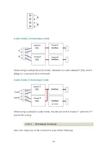
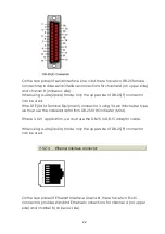
Page 23: ...23 When using 4 wire 2 pairs mode only the upper side of RJ 45 connector can be used ...
Page 37: ...37 3 5 1 Menu Tree diagram 2 wire mode ...
Page 38: ...38 3 5 2 Menu Tree diagram 4 wire mode ...
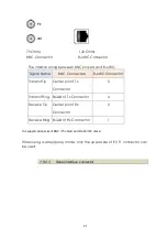
Page 52: ...52 75 Ohms 120 Ohms BNC Connector RJ 45 Connector ...
Page 59: ...59 ...
Page 78: ...78 ...
Page 82: ...82 3 8 2 4 Series interface 4 wire mode 3 8 2 5 Ethernet interface 2 wire mode ...
Page 83: ...83 3 8 2 6 Ethernet interface 4 wire mode ...
Page 84: ...84 3 8 2 7 T1 interface 2 wire mode 3 8 2 8 T1 interface 4 wire mode ...
Page 86: ...86 3 8 3 3 Ethernet interface For Ethernet interface model ...
Page 87: ...87 3 8 3 4 T1 interface For T1 interface model ...
Page 105: ...105 Ethernet Rate Auto Speed Duplex ...
Page 113: ...113 side Click Reset button and the values will be set to default ...
Page 116: ...116 4 5 7 4 SNMP All SNMP parameter must setup on this item ...
Page 128: ...128 cable ...
Page 131: ...131 ...
Page 136: ...136 ...
Page 137: ......
Page 138: ......

