


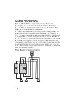

INTRODUCTION
We congratulate you on choosing your new marina shore power system. This system is a
member of a family of marine products from CTEK Sweden AB. The shore power system
has been developed to satisfy the stringent requirements for functionality and environme-
and using the system.
SAFETY
WARNING!
This system has been designed and approved for installation by those who
required for installing the system. For this reason it is prohibited to make any adjust-
threatening consequences to people in and around the boat. Approved for installation
! "
!
#
WARNING!
This system must not be used without proper installation of the electrical
cabinet according to attached installation instruction
WARNING!
The power feed from the shore may not be connected to the boat before
the entire system has been installed in the boat. Connecting the power from an outside
source otherwise risks exposing people in and around the boat to life threatening
hazards.
WARNING!
The shore power system’s protective earth must be electrically connected
with all the electrically conductive devices in the boat that have a connection to earth,
for example, via the water. Failure to do this will result in immediate mortal danger to
people in or around the boat in the event of a fault to the electrical equipment con-
nected to the shore power system.
WARNING!
! $$ %
injury in the event of a fault in one of the electrical devices connected to the system, the
system’s electrical cabinet must be a part of the installation.
WARNING!
The electrical cabinet on shore, that the shore power cable is connected
to, should be regarded as a part of the installation. This is because the shore power
system’s protective earth must be able to provide protection against personal injury in
the event of a fault in any part of the system.


