background image


SYSTEM DESCRIPTION

8 ^&_   5/*Y$

The shore power cable is connected at one end to the electrical cabinet on shore.  
The other end is connected to the boat’s electrical power inlet. The internal electrical 
cabinet is fed via an internal cable from the power inlet.

^ $  $ -
< 6%"/*=  $ < 6)J"  =
^;)%  I5^I*-
tion is designed to be an electrical earthing point for all the live components on the boat.

^   $%  %
DC currents from causing galvanic corrosion. The galvanic isolator blocks the current 
that is caused by a potential difference of up to 1VDC between the earth potential on the 
boat and the earth potential on shore The galvanic isolator handles short circuit currents 
)"+**6 )J  $ < "  =
without being damaged or degraded.

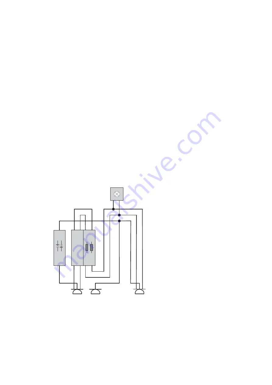
Wiring diagram for electrical cabinet:

F1

2xC16

L1

N

PE

X1

Type 1019

X2

Type 1020

EFB

2-pole

GI

H1

X0

L1

N

PE

Summary of Contents for Daycruiser

Page 1: ...AC POWER SYSTEM DAYCRUISER User instructions and installation guide EN...

Page 2: ...en installed in the boat Connecting the power from an outside source otherwise risks exposing people in and around the boat to life threatening hazards WARNING The shore power system s protective eart...

Page 3: ...le who are partially or fully in the water WARNING hull As a result of this the greatest possible caution must be observed to ensure that no form of leakage occurs where peripheral lake or sea water m...

Page 4: ...e system components and cables Check that the length of the cables is suf Assembly of power inlet 6 4 602 6 0 602 4 Note that the enclosed gasket is to be located between the inlet and the wall it is...

Page 5: ...position Now snap on the cover and frame again Assembly of cables Connect the internal cables to the system components power inlet electrical cabinet and panying dismantling tools must be used NOTE E...

Page 6: ...d to power inlet 5 5 5 Y 16A AC 5 552 6 2J 65 Power inlet Dimension Length of connection lead 6 lead Voltage Current Weight 0 6 lead not included GJ4 5 5 5 Y 16A AC X Electrical cabinet 8 6 Conductor...

Page 7: ...Wall socket surface mounted single 8 6 Conductor area Voltage Current Weight J J 2 G 5 5 5 Y 16A AC 2...

Page 8: ...be an electrical earthing point for all the live components on the boat DC currents from causing galvanic corrosion The galvanic isolator blocks the current that is caused by a potential difference o...

Page 9: ...System overview...

Page 10: ...or material The customer must return the product together with the receipt of purchase to the point of purchase This warranty is void if components in the shore power system are handled carelessly ope...

Reviews: