CN7 (DC-IN)
Pin
Description
1
DC-IN
2
GND
3
C-GND
CN9 (SPK)
Pin
Description
1
OUTA-
2
OUTA+
3
OUTB-
4
OUTB+
System Engine
3.4 Connector Pin Assignments
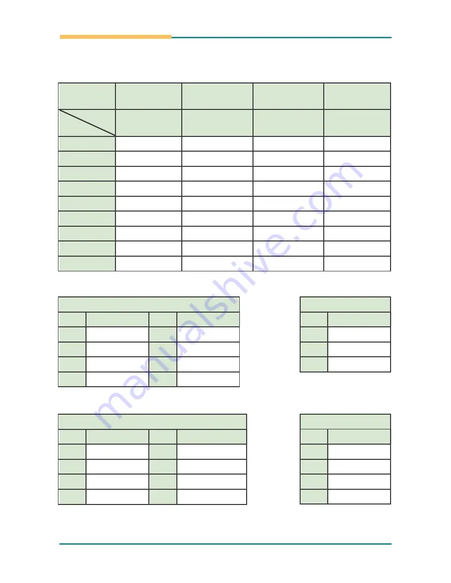
Connector
CN11
(COM 2/3/4)
CN12 ~ CN13
(COM 3/4)
CN12 ~ CN13
(COM 3/4)
CN13
(COM4)
Mode
Pin
RS-232
RS-422
RS-485
CAN*
1
DCD
422TX-
485D-
2
RXD
422TX+
485D+
CAN_L
3
TXD
422RX+
4
DTR
422RX-
5
GND
GND
GND
GND
6
DSR
7
RTS
CAN_H
8
CTS
9
RI
*Note
:
CAN mode is a reserved function. It's not available on 2500-VP15-E.
CN5 (USB1/USB2)
Pin
Description
Pin
Description
1
+5V
5
+5V
2
USB0-
6
USB1-
3
USB0+
7
USB1+
4
GND
8
GND
CN6 (PS/2 KB & MS)
Pin
Description
Pin
Description
1
KDAT
5
KCLK
2
MDAT
6
MCLK
3
GND
7
GND_EARTH
4
KMVCC
8
GND_EARTH
- 20 -
Summary of Contents for 2500-VP15
Page 2: ...P N 4017156100110P 2013 12...
Page 3: ...This page is intentionally left blank 2...
Page 8: ...Chapter 1 General Informa tion General Information Chapter1 1 General Information 1...
Page 14: ...Chapter 2 System Setup System Setup Chapter2 2 System Setup 7...
Page 20: ...System Setup 2 2 4 VESA Mounting Optional VESA bracket VESA 100 VESA 75 13...
Page 21: ...This page is intentionally left blank 14...
Page 22: ...Chapter 3 System Engine System Engine Chapter3 3 System Engine 15...
Page 29: ...This page is intentionally left blank 22...
Page 41: ...This page is intentionally left blank 34...
Page 42: ...Language Setup Chapter5 5 Language Setup 35...
Page 46: ...Chapter 6 System Tuning System Tuning Chapter6 6 System Tuning 39...
Page 51: ...This page is intentionally left blank...
Page 52: ...Chapter 7 Maintenance Maintenance Chapter7 7 Maintenance 45...


