DUAL ACTION SETUP
Applicator Nose Installation
Depending on the length of the swing arm, some applicator noses will be too big to leave on the
applicator for shipping. The following instructions will help in re-installing the applicator nose.
If the dual action tamp assembly is removed from the applicator in shipping, the mounting arm
will still be installed. Remove the applicator and mount on a stand in a nose down attitude.
This faceplate is used for mounting the valve bank. The mounting arm that supports the dual
action tamp is bolted to the side or what is now the bottom of the applicator and extends out in
front of where the label comes out of the printer. There is a ¼” recess in the plate with four ¼”
slots. This is where the slide of the dual action tamp is mounted. Take the tamp assembly and set
it (slide body) in the recess and used the four ¼” shcs. and the stainless nut plate to secure it in
position. These same screws will be later be used for the up and down adjustment of the label
pad to the peel edge.
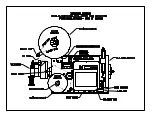
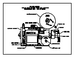
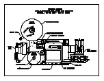
Figure 20 (dual action tamp assembly)
With everything in place, reconnect the air lines. The air lines should be marked as to where they
go. Make sure when routing the lines that they do not hit or rub anything when the assembly
actuates. Pay special attention to the 3/8 air blast/vacuum line going to the manifold.
b5-2
Summary of Contents for 3600-PA
Page 8: ......
Page 9: ......
Page 10: ......
Page 11: ......
Page 12: ......
Page 13: ......
Page 14: ......
Page 15: ......
Page 16: ......
Page 17: ......
Page 66: ......
Page 67: ......
Page 68: ......
Page 69: ......
Page 70: ......
Page 71: ......
Page 72: ......
Page 73: ......
Page 74: ......
Page 75: ......
Page 76: ......
Page 77: ......
Page 78: ......
Page 79: ......
Page 80: ......
Page 81: ......
Page 82: ......
Page 83: ......
Page 84: ......
Page 85: ......
Page 86: ......
Page 87: ......
Page 88: ......
Page 89: ......
Page 90: ......
Page 91: ......
Page 92: ......
Page 93: ......
Page 94: ......
Page 95: ......
Page 96: ......
Page 97: ......
Page 98: ......
Page 99: ......
Page 100: ......
Page 101: ......
Page 102: ......
Page 103: ......
Page 104: ......
Page 105: ......
Page 106: ......
Page 107: ......
Page 108: ......
Page 109: ......
Page 110: ......
Page 111: ......
Page 112: ......
Page 113: ......
Page 114: ......
Page 115: ......
Page 120: ......
Page 121: ......
Page 122: ......
Page 123: ......
Page 143: ......
Page 144: ......
Page 145: ......
Page 146: ......
Page 147: ......
Page 148: ......
Page 149: ......
Page 150: ......
Page 151: ......
Page 152: ......
Page 153: ......
Page 154: ......
Page 155: ......
Page 163: ...APPLY SEQUENCE Figure 28 c3 4 ...
Page 164: ......
Page 165: ......
Page 166: ......
Page 167: ......
Page 168: ......
Page 169: ......
Page 170: ......
Page 177: ......
Page 178: ......
Page 179: ......
Page 180: ......
Page 181: ......
Page 182: ......
Page 183: ......
Page 184: ......
Page 185: ......
Page 186: ......
Page 187: ......


