CORNER WRAP SETUP
CORNER WRAP SETUP
Corner Wrap Setup
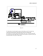
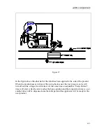
Position the applicator so the product will contact the extended label pad such that the label will
wipe around the corner in the proper vertical and horizontal position. The “product detect”
sensor,
which should always be set to leading edge detection
, will have to be positioned so the
applicator will have enough time to swing out in front of the product. After the extend time, the
tamp/swing pressure will be reduced so it will take less force to collapse the swing arm. This will
help lighter products push through the swing arm. To reduce the pressure on the arm in this
position, adjust the precision regulator that is mounted on the valve bank and is plumbed into the
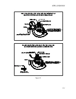
“low pressure swing” valve. The swing arm will stay extended to fold the label around the
product until the “swing back” sensor sees the product. This sensor should be positioned so the
swing arm stays in contact to the product until the label is finished being applied.
Standard Corner Wrap Apply Sequence
If the customer wants to use the standard apply sequence, the ASS-214-0111RM or ASS-214-
0111LM valve bank assembly is required. The applicator is waiting with a label on the pad and
label formats in the print buffer. When the product triggers the product detect sensor, the swing
arm extends out into the product flow. At the same time, the “tamp extend” timer will start. At the
end of the “tamp extend” timer, the tamp air pressure will lower to what was set on the precision
regulator. This will cause the swing arm to act like it is spring-loaded. At same time the pressure
is dropped to the swing arm, the vacuum is turned off to the pad and remains off during the apply
cycle. This reduces the amount of “label drag” during the apply cycle. There could be a slight air
blast to aid in getting the label onto the product, if required. The air blast pressure is factory set to
0 psi. When the product activates the “swing back” sensor, the air blast (if enabled) stops,
vacuum resumes to the label pad, the valve switches to high pressure, and the swing arm returns
to the home position. At the end of the tamp retract timer if formats are in the print buffer another
label is printed and fed out onto the pad. The sequence is now ready to be repeated.
Vacuum Off Option:
The vacuum off option is dependant upon the valve bank piping /
configuration. If the customer wants to use the vacuum off option ASS-214-0112RM or ASS-
214-0112LM valve bank assembly is required. The following section will explain the “vacuum
off” apply sequence.
Vacuum Off Apply Sequence
The Vacuum Off option can be useful in conserving air between label applications if only one
format is sent to the printer for each product being labeled because the vacuum will remain off
until the next label is printed and fed out onto the pad. This option also keeps dirt particles from
entering the pad, which over time will affect labeling performance. The applicator is waiting with
a label on the tamp pad and label formats in the print buffer. When the product triggers the
“product detect” sensor, the swing arm will extend out into the product flow. At the same time,
the “tamp extend” timer will start. At the end of the “tamp extend” timer, the swing air pressure
will lower to what was set on the precision regulator. This will cause the swing arm to act like it
is spring-loaded. As the pressure is dropped to the swing arm, the vacuum is turned off to the pad.
The product will travel into the label pad splitting the label so half will be applied to the front of
the product and the rest is wiped down the side. When the product activates the “swing back”
sensor, the valve switches to high pressure, the tamp retract timer starts and the label pad returns
home. If there are formats in the print buffer at the end of the tamp retract timer the vacuum to the
label pad will turn back on as another label is printed and fed out onto the pad. The sequence is
now ready to be repeated.
c2-1
Summary of Contents for 3600-PA
Page 8: ......
Page 9: ......
Page 10: ......
Page 11: ......
Page 12: ......
Page 13: ......
Page 14: ......
Page 15: ......
Page 16: ......
Page 17: ......
Page 66: ......
Page 67: ......
Page 68: ......
Page 69: ......
Page 70: ......
Page 71: ......
Page 72: ......
Page 73: ......
Page 74: ......
Page 75: ......
Page 76: ......
Page 77: ......
Page 78: ......
Page 79: ......
Page 80: ......
Page 81: ......
Page 82: ......
Page 83: ......
Page 84: ......
Page 85: ......
Page 86: ......
Page 87: ......
Page 88: ......
Page 89: ......
Page 90: ......
Page 91: ......
Page 92: ......
Page 93: ......
Page 94: ......
Page 95: ......
Page 96: ......
Page 97: ......
Page 98: ......
Page 99: ......
Page 100: ......
Page 101: ......
Page 102: ......
Page 103: ......
Page 104: ......
Page 105: ......
Page 106: ......
Page 107: ......
Page 108: ......
Page 109: ......
Page 110: ......
Page 111: ......
Page 112: ......
Page 113: ......
Page 114: ......
Page 115: ......
Page 120: ......
Page 121: ......
Page 122: ......
Page 123: ......
Page 143: ......
Page 144: ......
Page 145: ......
Page 146: ......
Page 147: ......
Page 148: ......
Page 149: ......
Page 150: ......
Page 151: ......
Page 152: ......
Page 153: ......
Page 154: ......
Page 155: ......
Page 163: ...APPLY SEQUENCE Figure 28 c3 4 ...
Page 164: ......
Page 165: ......
Page 166: ......
Page 167: ......
Page 168: ......
Page 169: ......
Page 170: ......
Page 177: ......
Page 178: ......
Page 179: ......
Page 180: ......
Page 181: ......
Page 182: ......
Page 183: ......
Page 184: ......
Page 185: ......
Page 186: ......
Page 187: ......


