APPLICATOR SETUP
Extended Peel Edge Assembly
This nose assembly is used when it is desired to disable the backfeed option on the applicator to
gain more labels per minute. With the backfeed off, the leading edge of labels will stop in
different places with different length labels. To overcome this, the print engine is set to stop the
label with the label leading edge under the print line of the printhead, and the tamp assembly is
adjusted to where the label stops at the extended peel edge for proper dispensing.
Note
: With this type of arrangement, there will always be one or more labels
between the printhead and the extended peel edge.
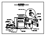
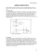
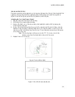
The extended peel edge assembly is mounted on the label feed side of the applicator using four ¼
shcs. and two 3/16 dowel pins. There are also two ¼ shcs. used to mount the two guide rods to
the side of the machine. To move the label pad closer to the peel edge, loosen the two 1/4 shcs.
marked as tamp in/out adjustment in Figure 4. When the label pad is in position, re-tighten the
screws. To raise or lower the label pad to the peel edge, loosen the two ¼ shcs. in the slide body
(marked as up/down in Figure 4). The label pad can be moved side to side using the four #10
shcs. in the manifold. To move the whole assembly in or out so the peel edge lines up with the
leading edge of the label, loosen the clamping screws on the guide rods and turn the assembly
adjustment knob. Tighten all screws when finished.
The plumbing will be the same as the standard tamp assembly except for the air assist. Instead of
it plumbing into the air assist tube, it will plumb into a straight tube at the same place. This tube
will transfer air through the faceplate and across the printer between the web path going to the
pad and the return path of the liner. This tube is held with same holder that was used to hold the
assist tube on the standard tamp except it’s mounted on the inside of the machine. From the end
of the pass through tube to the air assist tube, a ¼’ air line is attached.
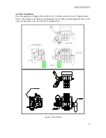
Figure 4 (extended peel edge assembly)
7-4
Summary of Contents for 3600-PA
Page 8: ......
Page 9: ......
Page 10: ......
Page 11: ......
Page 12: ......
Page 13: ......
Page 14: ......
Page 15: ......
Page 16: ......
Page 17: ......
Page 66: ......
Page 67: ......
Page 68: ......
Page 69: ......
Page 70: ......
Page 71: ......
Page 72: ......
Page 73: ......
Page 74: ......
Page 75: ......
Page 76: ......
Page 77: ......
Page 78: ......
Page 79: ......
Page 80: ......
Page 81: ......
Page 82: ......
Page 83: ......
Page 84: ......
Page 85: ......
Page 86: ......
Page 87: ......
Page 88: ......
Page 89: ......
Page 90: ......
Page 91: ......
Page 92: ......
Page 93: ......
Page 94: ......
Page 95: ......
Page 96: ......
Page 97: ......
Page 98: ......
Page 99: ......
Page 100: ......
Page 101: ......
Page 102: ......
Page 103: ......
Page 104: ......
Page 105: ......
Page 106: ......
Page 107: ......
Page 108: ......
Page 109: ......
Page 110: ......
Page 111: ......
Page 112: ......
Page 113: ......
Page 114: ......
Page 115: ......
Page 120: ......
Page 121: ......
Page 122: ......
Page 123: ......
Page 143: ......
Page 144: ......
Page 145: ......
Page 146: ......
Page 147: ......
Page 148: ......
Page 149: ......
Page 150: ......
Page 151: ......
Page 152: ......
Page 153: ......
Page 154: ......
Page 155: ......
Page 163: ...APPLY SEQUENCE Figure 28 c3 4 ...
Page 164: ......
Page 165: ......
Page 166: ......
Page 167: ......
Page 168: ......
Page 169: ......
Page 170: ......
Page 177: ......
Page 178: ......
Page 179: ......
Page 180: ......
Page 181: ......
Page 182: ......
Page 183: ......
Page 184: ......
Page 185: ......
Page 186: ......
Page 187: ......


