Pigeon 2.0
User’s Guide
___ www.ctr-electronics.com ______________________ 1/31/2022
Cross The Road Electronics Page 20 ____________________________ 1/31/2022
6. Orientation Convention
6.1.
World Frame Reference
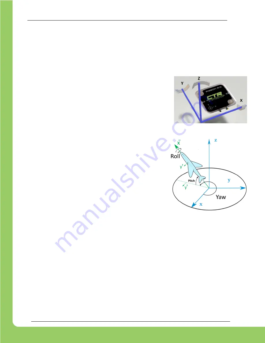
Pigeon2 X as the forward axis, +Y as the left axis, and +Z towards the sky (right-hand orientation). In
researching common axis orientations, this is a common way to define the world frame reference for ground-
based vehicles.
When the Pigeon is using the
Default Mount Orientation
, these
axes match
the XYZ logo on the enclosure
.
6.2.
Euler Angles
For applications that require
Euler Angles (Yaw, Pitch, Roll)
to represent the
pose within the world frame reference, Pigeon2 performs the following:
•
First calculate
Yaw
by rotating about
+Z
in the
world frame reference
. (Turning to the left is positive).
•
From this new body frame, calculate
Pitch
about the
IMU’s
local reference
Y’
(Pitching nose down is positive,
diagram demonstrates a negative pitch).
•
Calculate a final
Roll
about the
IMU’s local
reference
X’’
.
Note that because
Yaw
is calculated first, it is done so in the
world frame
reference
(defined by gravity)
. Because of this, Yaw is defined as travel
about the plane orthogonal to gravity. Therefore, the Pigeon 2.0
does not
require being aligned to gravity for reliable Yaw.
6.3.
Gimble Lock
Given the angle definitions used by Pigeon 2.0,
Gimble Lock
occurs when
the
Pitch reaches near ±90 degrees
.
At this location the tip of the airplane would be aligned with
World Frame
Reference Z Axis
. At this point
Roll
and
Yaw
cannot be distinguished
from each other. As a result, the Euler
Angles are not reliable near this orientation.
For applications that
require 360 degrees of vertical travel
, it is strongly recommended to use
Roll
instead of
Pitch
.
Roll
allows for complete 360 rotation with no risk of ambiguity. This is because
Roll
is the
final calculated
angle
and cannot introduce ambiguity if
Pitch
is sufficiently away from Gimble Lock.
Note that Gimble Lock is a
limitation
of using
Euler Angles
. In other words, there is always a location that
produces this erroneous condition. More advanced applications may avoid this by using:
-
Gravity Vector
-
Quaternion
–
which can provide the Line of Rotation (LOR), and amount of rotation over LOR
-
Combinations of the above with or without Euler Angles
But for relatively simple applications (ground vehicle, single axis arms, etc.), simply choosing an IMU orientation
that will not encounter Gimble Lock is sufficient.


