


Pigeon 2.0
User’s Guide
___ www.ctr-electronics.com ______________________ 1/31/2022
Cross The Road Electronics Page 8 ____________________________ 1/31/2022
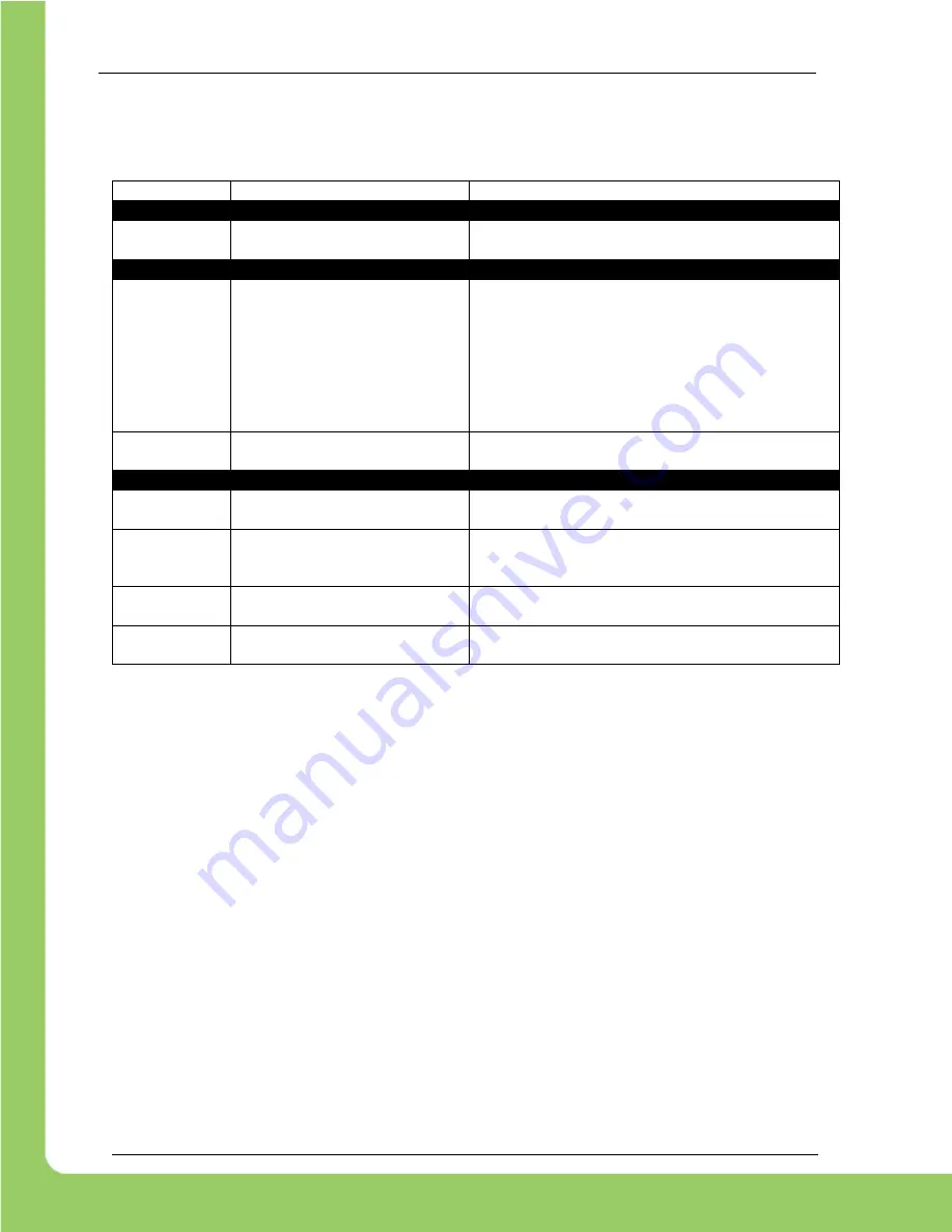
1.5. LED States
The Pigeon 2.0 features 2 tri color LEDs that indicate CAN bus health. This feature can be used to confirm proper
CAN bus wiring. The table below shows the possible color states.
LED Color
Blink Pattern
Description
Off
Pigeon 2.0 is not powered/ plugged in.
Check power cabling to the Pigeon 2.0.
Yellow
/
Green
Only one LED will blink this
pattern.
Device is in bootloader, most likely because field-
upgrade failed in middle of event.
Inspect CAN bus wiring and re-field-upgrade using
Phoenix Tuner.
If device has valid firmware, turn device off, wait 10
seconds, and turn device on to boot strap it.
Red
/
Yellow
LEDs are never off
–
one of the
two colors are
always illuminated
Hardware is damaged
Red Blink
Check CAN Bus health and connection to the Pigeon
2.0.
Yellow
Alternate Blinking
(Note 1)
CAN bus detected.
Robot controller is not present on CAN bus, or Pigeon2
software object not created in user application.
Yellow
Simultaneous Blinking
(Note 2)
CAN bus detected.
Robot is disabled.
Green Blink
CAN bus detected.
Robot is enabled.
Note 1:
Only one LED is on at any given moment.
Note 2:
Both LEDs are on at the same time.


