7
1.3 Front & Rear Panel
Front Panel
The front panel is configured as follows:
1. 24 x 10/100/1000Base-T RJ-45 ports (Ports 1-24)
2. 4 x Gigabit combo ports (Ports 25-28) :
4 x 10/100/1000Base-T RJ-45 ports, or
4 x 100/1000Base-X SFP ports
3. Reset Button:
Pressing reset button for 2 seconds then release to restart the
system.
Pressing reset button for 10 seconds then release to reset the
Managed Switch back to factory settings and restart the system.
4. Console port:
An asynchronous serial console port supporting the RS-232
electrical specification. The console port can be used to
manage the device and the interface should be configured to
9600 , N , 8 ,1
5. LED:
Please refer to chapter
Rear Panel
The Managed Switch provides one fixed power module or two power modules
for redundancy purpose. Depending on your physical environment
requirements, the type of power module is selectable and could be either AC
input or DC input.
The rear panel is configured as follows:
Power module and Connector:
AC power connection: 100-240V , 50/60Hz
DC power connection: 48VDC
Please refer to chapter
1.4 Cable Specifications
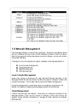
The following table contains various cable specifications for the Managed
Switch. Please make sure that you use the proper cable when connecting the
Managed Switch.
1
2
3
4
5


