background image


Series 4 Module User Guide—North America 

| Page 6 of 17 


4


Installation 


4.1


Mounting 


!


Physically damaged modules may cause ground faults and associated electrical hazards. To avoid these conditions:


!


Do not install the modules during high wind or wet conditions to reduce the likelihood of injury.


Wear safety glasses (ANSI Z87.1-2003) and cut-resistant gloves when working on non-interconnected modules or 


!


systems.


!


Wear electrically rated PPE when working on interconnected modules or system components.


Handle modules with care during installation, as heavy impact on the front, back, or edges could result in damage 

to the module. Do not walk or stand on modules or retaining clips.


Do not stack or carry multiple modules on top of one another after removal from factory packaging to minimize 

the risk of breakage.


Do not lift or pull on modules using lead wires or strain relief wire loops to minimize the risk of wire damage.


Mounting of the Series 4 and Series 4A Module to a suitable structure can be done by attaching the module directly to the 
structure using retaining clips (see Figure 5.1). 


Any  module  without  a  frame  (laminate)  shall  not  be  considered  to  comply  with  the  requirements  of  UL  1703  unless  the 
module  is  mounted  with  hardware  that  has  been  tested  and  evaluated  with  the  module  under  this  standard  or  by  a  field 
inspection certifying that the installed module complies with the requirements of UL 1703. The Series 4 and Series 4A Module 
is a frameless laminate and is considered to be in compliance with UL 1703 only when the module is mounted using approved 
hardware in the manner specified by the mounting instructions in Chosen Techno Solar Private Limited Application Note PD-5-
320-04 NA. 


Additional mounting systems may be approved for use. The interface of the mounting structure to the module (including the 
retaining  clip  and  rubber  insulator)  must  meet  the  technical  requirements  specified  in  Chosen  Techno  Solar  Private  Limited 
Application Note PD-5-320-04 and must be approved  for use by Chosen Techno Solar Private Limited prior to installation. The 
mounting system design must provide adequate support for the module to prevent damage from occurring when the module is 
subjected to pressures of 2400Pa (which equates to wind pressure of 130km/h (80.8 mph), with a safety factor of 3 for gusty 
conditions based on IEC 61646 / IEC 61215). The location of the clips shall be along the 1200mm (47.25 in) length of the module 
and the center point of the clip shall be located between 250mm (9.84 in) and 300mm (11.81 in) from the module edge. See 
Figure 5.1 for allowed location. Rubber insulator material, or equivalent must be used between the module and both the clip 
and mounting structure to provide adequate protection of the module and must meet all requirements described in PD-5-320-
04 Module Mounting. No direct contact of rigid structures is permitted against the surface or edges of the module. 


All mounting structures must provide a flat plane for the modules to be mounted on, and must not cause any twist or stress to 
be placed on the module. 


Modules should not be installed in a way that restricts air circulation to the underside of the module. Modules generate 
heat and require adequate airflow for cooling. 


PD-5-200-04 NA | REV 3.1 | 0348_UG_NA_11JUL17 

Chosen Techno Solar Private Limited 

Summary of Contents for FS-4100

Page 1: ...User Guide User Guide Chosen Techno Solar Private Limited Series 4 Module North America REV 3 1 PD 5 200 04 NA 0348_UG_NA_11JUL17...
Page 2: ...1 System Derating Factors 5 4 Installation 6 4 1 Mounting 6 4 2 Module Orientation 8 4 3 Module Shading Considerations 8 4 4 Electrical Interconnection 9 5 Mechanical Specifications Drawings 12 6 Prop...

Page 3: ...lers and maintenance personnel Read this User Guide thoroughly before beginning any work related to the installation operation or maintenance of the Chosen Techno Solar Private Limited Series 4 or Ser...
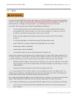
Page 4: ...Chosen Techno Solar Private Limited module reverse current overload may result in module failure including module breakage Extreme and continuous reverse current overload conditions may cause a fire...

Page 5: ...ized or Listed by Underwriters Laboratories UL for their intended purpose Ensure the PV array open circuit voltage does not exceed 1500VDC 1000VDC for UL Canada Install modules with mounting systems t...

Page 6: ...2 FS 4105 2 FS 4107 2 FS 4110 2 FS 4112 2 FS 4100A 2 FS 4102A 2 FS 4105A 2 FS 4107A 2 FS 4110A 2 FS 4112A 2 Nominal Power 5 PMPP W 100 0 102 5 105 0 107 5 110 0 112 5 Voltage at PMA X VMPP V 66 2 67...

Page 7: ...tage VSYS V 1500 2 Maximum Series Fuse ICF A 4 0 1 As received and stabilized ratings at Standard Test Condition 1000W m2 AM 1 5 25 C Cell Temperature 10 2 1000V Listed for UL Canada 3 Measurement unc...

Page 8: ...d using approved hardware in the manner specified by the mounting instructions in Chosen Techno Solar Private Limited Application Note PD 5 320 04 NA Additional mounting systems may be approved for us...

Page 9: ...eight is 3 25 in 82 55 mm Modules used in UL Listed rooftop applications must be installed with approved mounting systems If alternate mounting means are employed this may affect the Listing fire clas...

Page 10: ...from diffuse shading for objects greater than 2 meters or 7 feet There is a low risk of module damage due to shading from walking or standing in front of operating modules or from parking or driving...

Page 11: ...lead wires tight at any time After installation the connected wire must not be under stress or tension Do not use junction box assembly or lead wire strain relief loops to secure excess wire or to be...

Page 12: ...re inverter ratings are appropriate When connecting Chosen Techno Solar Private Limited Series 4 and or Series 4A Modules in a series string ensure that the system design voltage and inverter design s...

Page 13: ...unded ungrounded floating and bi polar system architectures provided all appropriate design requirements are met and approved by First Solar FS Series PV Modules should not be used in positive grounde...

Page 14: ...on Span2 1314 mm 51 73 in Weight 12 kg 26 5 lbs Fire Performance Type3 Type 10 Module Class A Spread of Flame Class B Burning Brand Operating Temperature 40 C to 85 C 1Minimum from strain relief to co...

Page 15: ...ng in landscape orientation is acceptable Module row to row shading in portrait orientation is prohibited Strain relief cable ties must not be removed If module cleaning is undertaken modules must be...

Page 16: ...visit www firstsolar com recycling for further details on the recycling program It is normal for the modules to exhibit visual irregularities which do not impact power Series 4A Modules with anti refl...

Page 17: ...otice Accordingly the reader is cautioned to verify that data sheets are current before placing orders or finalizing system permitting and or design Information furnished by Chosen Techno Solar Privat...

Page 18: ...Series 4 PV Module Mounting for UL Applications PD 5 308 FS Series PV Modules Reverse Current Overload PD 5 320 04 FS Series 4 PV Module Mounting PD 5 804 FS Series PV Module Cleaning Guidelines PD 5...

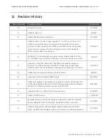
Page 19: ...to 2 2 Section 4 1 1 Added comment to Section 7 on cleaning risk of damage 12 17 2017 Added Section 10 for Doc References Revised order of Warnings in Sections 2 3 Added electrical ratings for FS 4xx...

Reviews: