background image

3

S

ection

 1 — i

mportant

 S

afe

 o

peration

 p

racticeS

5. 

Never run an engine indoors or in a poorly ventilated area. Engine 

exhaust contains carbon monoxide, an odorless and deadly gas. 

6. 

Do not operate machine while under the influence of alcohol or 

drugs. 

7. 

Muffler and engine become hot and can cause a burn. Do not touch. 

Keep children away.

8. 

Exercise extreme caution when operating on or crossing gravel 

surfaces. Stay alert for hidden hazards or traffic.

9. 

Exercise caution when changing direction and while operating on 

slopes.  Do not operate on steep slopes.

10. 

Plan your snow-throwing pattern to avoid discharge towards 

windows, walls, cars etc. Thus, avoiding possible property damage 

or personal injury caused by a ricochet. 

11. 

Never direct discharge at children, bystanders and pets or allow 

anyone in front of the machine. 

12. 

Do not overload machine capacity by attempting to clear snow at 

too fast of a rate.

13. 

Never operate this machine without good visibility or light. Always 

be sure of your footing and keep a firm hold on the handles. Walk, 

never run.

14. 

Release auger control lever to disengage power to the auger when 

transporting or not clearing snow.

15. 

Never operate machine at high transport speeds on slippery 

surfaces. Look down and behind and use care when backing up. 

16. 

After striking a foreign object or if the machine should start to 

vibrate abnormally, stop the engine, disconnect the spark plug wire 

and ground it against the engine. Inspect thoroughly for damage. 

Repair any damage before starting and operating.

17. 

Disengage all control levers and stop engine before you leave the 

operating position (behind the handles). Wait until the auger comes 

to a complete stop before unclogging the chute assembly, making 

any adjustments, or inspections. 

18. 

Never put your hand in the discharge or collector openings. Always 

use the clean-out tool provided to unclog the discharge opening. 

Do not unclog chute assembly while engine is running. Shut off 

engine and remain behind handles until all moving parts have 

stopped before unclogging.

19. 

Use only attachments and accessories approved by the 

manufacturer (e.g. wheel weights, tire chains, cabs etc.).

20. 

When starting engine, pull cord slowly until resistance is felt, then 

pull rapidly. Rapid retraction of starter cord (kickback) will pull hand 

and arm toward engine faster than you can let go. Broken bones, 

fractures, bruises or sprains could result.

21. 

If situations occur which are not covered in this manual, use care 

and good judgment. Contact Customer Support for assistance and 
the name of your nearest servicing dealer.

Clearing a Clogged Discharge Chute

Hand contact with the rotating impeller inside the discharge chute is the 

most common cause of injury associated with snow throwers. Never use 

your hand to clean out the discharge chute.
To clear the chute:
1. 

SHUT THE ENGINE OFF!

2. 

Wait 10 seconds to be sure the impeller blades have stopped 

rotating.

3. 

Always use a clean-out tool, not your hands.

Maintenance & Storage

1. 

Never tamper with safety devices. Check their proper operation 

regularly. Refer to the maintenance and adjustment sections of this 

manual.

2. 

Before cleaning, repairing, or inspecting machine disengage all 

control levers and stop the engine. Wait until the auger come to a 

complete stop. Disconnect the spark plug wire and ground against 

the engine to prevent unintended starting. 

3. 

Check bolts and screws for proper tightness at frequent intervals to 

keep the machine in safe working condition. Also, visually inspect 

machine for any damage. 

4. 

Do not change the engine governor setting or over-speed the 

engine. The governor controls the maximum safe operating speed of 

the engine.

5. 

Snow thrower shave plates and skid shoes are subject to wear and 

damage. For your safety protection, frequently check all components 

and replace with original equipment manufacturer’s (OEM) parts 

only. “Use of parts which do not meet the original equipment 

specifications may lead to improper performance and compromise 

safety!”

6. 

Check control levers periodically to verify they engage and 

disengage properly and adjust, if necessary. Refer to the adjustment 

section in this operator’s manual for instructions.

7. 

Maintain or replace safety and instruction labels, as necessary.

8. 

Observe proper disposal laws and regulations for gas, oil, etc. to 

protect the environment.

9. 

Prior to storing, run machine a few minutes to clear snow from 

machine and prevent freeze up of auger.

10. 

Never store the machine or fuel container inside where there is 

an open flame, spark or pilot light such as a water heater, furnace, 

clothes dryer, etc.

11. 

Always refer to the operator’s manual for proper instructions on 

off-season storage.

12. 

Check fuel line, tank, cap, and fittings frequently for cracks or leaks. 

Replace if necessary.

13. 

Do not crank engine with spark plug removed.

14. 

According to the Consumer Products Safety Commission (CPSC) and 

the U.S. Environmental Protection Agency (EPA), this product has an 

Average Useful Life

 of seven (7) years, or 60 hours of operation. At the 

end of the 

Average Useful Life

 have the machine inspected annually 

by an authorized service dealer to ensure that all mechanical and 

safety systems are working properly and not worn excessively. 
Failure to do so can result in accidents, injuries or death.

Do not modify engine

To avoid serious injury or death, do not modify engine in any way. 

Tampering with the governor setting can lead to a runaway engine and 

cause it to operate at unsafe speeds. Never tamper with factory setting of 
engine governor.

Notice Regarding Emissions

Engines which are certified to comply with California and federal EPA 

emission regulations for SORE (Small Off Road Equipment) are certified 

to operate on regular unleaded gasoline, and may include the following 

emission control systems: Engine Modification (EM), Oxidizing Catalyst (OC), 
Secondary Air Injection (SAI) and Three Way Catalyst (TWC) if so equipped.

Summary of Contents for 3X 30 TRAC

Page 1: ...rator s Manual FOR CUSTOMER SERVICE 1 800 668 1238 Form No 769 12277 May 11 2017 Safe Operation Practices 2 Assembly Set Up 5 Controls Operation 8 Service 11 Troubleshooting 14 Parts Warranty See Separate Supplement French 15 Table of Contents NOTE This Operator s Manual covers several models Features may vary by model Not all features in this manual are applicable to all models and the model depi...

Page 2: ...chine indoors 4 Never remove gas cap or add fuel while the engine is hot or running 5 Allow engine to cool at least two minutes before refueling 6 Never over fill fuel tank Fill tank to no more than inch below bottom of filler neck to provide space for fuel expansion 7 Replace gasoline cap and tighten securely 8 If gasoline is spilled wipe it off the engine and equipment Move machine to another ar...

Page 3: ...it 10 seconds to be sure the impeller blades have stopped rotating 3 Always use a clean out tool not your hands Maintenance Storage 1 Never tamper with safety devices Check their proper operation regularly Refer to the maintenance and adjustment sections of this manual 2 Before cleaning repairing or inspecting machine disengage all control levers and stop the engine Wait until the auger come to a ...

Page 4: ...are rotating blades inside WARNING ROTATING BLADES Keep hands out of inlet and discharge openings while machine is running There are rotating blades inside WARNING ROTATING AUGER Do not put hands or feet near rotating parts in the auger housing or chute assembly Contact with the rotating parts can amputate hands and feet WARNING THROWN OBJECTS This machine may pick up and throw objects which can c...

Page 5: ...sfaction at all times Throughout this manual all references to right and left side of the machine are observed from the operating position Thank You NOTE This Operator s Manual covers several models Features may vary by model Not all features in this manual are applicable to all models and the model depicted may differ from yours Tools Required Adjustable Wrench or Socket Set Needle Nose Pliers Ch...

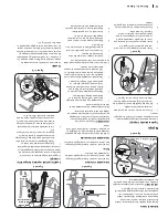
Page 6: ...Guides b Check that all cables are properly routed through the wire guide below the left side of the engine and the wire guide below the chute control head See Figure 2 8 b a c c Figure 2 8 Shear Pins Storage If Equipped On select units holes are provided in the rear of the handle panel for shear pin a and bow tie cotter pin b storage as shown in Figure 2 9 If not provided make sure to store them ...

Page 7: ...ired pitch setting a See Figure 2 13 To Increase the Distance Snow is Thrown Disengage lever from the current chute pitch setting Move the lever rearward to pivot the upper chute upward to the desired pitch setting a See Figure 2 13 TWO WAY CHUTE PITCH CONTROL CHUTE TILT DOWN CHUTE TILT UP TWO WAY INDEXED CHUTE PITCH CONTROL CHUTE TILT DOWN CHUTE TILT UP a Figure 2 13 Auger Control Test WARNING Pr...

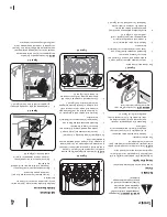
Page 8: ...pped The shift lever is located on the handle panel and is used to determine ground speed and direction of travel Forward There are six forward F speeds Position one 1 is the slowest and position six 6 is the fastest Reverse There are two reverse R speeds Position one 1 is the slower and position two 2 is the faster Chute Assembly Snow drawn into the auger housing is discharged out the chute assem...

Page 9: ...d wear on your machine s drive system Steering Trigger Controls If Equipped The left and right wheel steering trigger controls are located on the underside of the handles Refer to Figure 3 5 Figure 3 5 Squeeze the right trigger control to turn right Squeeze the left trigger control to turn left CAUTION Operate the snow thrower in open areas until you are familiar with these controls Overhead Chute...

Page 10: ...Part No 738 04124A gold colored replacement shear pins or 738 05273 Black colored replacement shear pins Any damage to the auger gearbox or other components as a result of failing to do so will NOT be covered by your snow thrower s warranty WARNING Always turn OFF the snow thrower s engine and remove the key prior to replacing shear pins The augers are secured to the spiral shaft with shear pins a...

Page 11: ...ide of housing Tighten securely See Figure 4 2 a b Figure 4 2 NOTE The shave plate on select units shown in Figure 4 3 have a wear edge that can be adjusted forward to prolong its life As the shave plate wears it can be moved into a second position To move adjustable shave plate if equipped 1 Allow engine to run until it is out of fuel Do not attempt to pour fuel from the engine 2 Carefully pivot ...

Page 12: ... freely 2 Engage drive control lever and gently attempt to push the unit forward The wheels should not turn The unit should not roll freely 3 If equipped with a shift lever with drive control lever released move shift lever back and forth between the R2 position and the F6 position several times There should be no resistance in the shift lever If any of the above tests failed the drive cable is in...

Page 13: ...or contact Customer Support Friction Wheel Inspection If unit fails to drive with drive control lever engaged and performing drive control cable adjustment fails to correct problem the friction wheel may need to be replaced NOTE Special tools are required and several components must be removed in order to replace the unit s friction wheel rubber See your authorized service dealer to have friction ...

Page 14: ... tracks in need of adjustment 1 Adjust drive control cable Refer to Service section 2 Replace drive belt Refer to Service section 3 Replace friction wheel Refer to Service section 4 Contact an authorized service center Unit fails to discharge snow 1 Chute assembly clogged 2 Foreign object lodged in auger 3 Auger control cable in need of adjustment 4 Auger belt loose or damaged 5 Shear pin s sheare...

Page 15: ...ffleuse n avance pas 1 Câble d entraînement mal réglé 2 Courroie d entraînement abîmée ou ayant du jeu 3 La roue de frottement est usée 4 Réglage nécessaire de la henille d entraînement 1 Réglez le câble d entraînement Voir le Réglages 2 Remplacez la courroie d entraînement 3 Remplacez la roue de frottement 4 Adressez vous à une station technique La souffleuse n évacue pas la neige 1 Goulotte d év...

Page 16: ... entraînement ou contactez le support client Inspection de la roue de frottement Si la souffleuse n avance pas lorsque la commande est enclenchée et si l ajustement du câble de commande ne parvient pas à corriger le problème il faudra peut être remplacer la roue de frottement NOTE Des outils spéciaux sont nécessaires et certaines pièces doivent être démontées pour remplacer le caoutchouc de la rou...

Page 17: ...nsmission comme suit 1 La commande de transmission débrayée poussez la souffleuse puis tirez la La machine doit bouger facilement 2 Embrayez la commande de traction et essayez de déplacer la souffleuse vers l avant Vous devez sentir une résistance Les roues ne doivent pas tourner La machine doit PAS bouger facilement 3 Débrayez la commande de la transmission déplacez plusieurs fois le levier de vi...

Page 18: ...Voir la Figure 4 2 a b Figure 4 2 NOTE La lame de raclage installée sur certain modèles représenté sur la Figure 4 3 ont un bord d usure qui peut être ajustée vers le devant pour prolonger sa durée de vie Lorsque la lame de raclage s use elle peut être déplacé dans une deuxième position Pour déplacer la lame de raclage si équipé 1 Laissez le moteur tourner jusqu à ce qu il tombe en panne d essence...

Page 19: ...oupilles de cisaillement AVERTISSEMENT Remplacez les goupilles de cisaillement avec les goupilles de cisaillement de rechange dorées 738 04124A ou avec les goupilles de cisaillement de rechange noires 738 05273 Tout dommage à la boîte d engrenage des tarières ou aux autres composants causé par le mauvais remplacement des goupilles de cisaillement NE sera PAS couvert par la garantie de la souffleus...

Page 20: ...arrière pour ajuster la distance d éjection de la neige Commande à 2 directions du déflecteur de la goulotte Pour réduire la distance d éjection de la neige Déplacez le levier vers l avant pour faire pivoter la goulotte supérieure vers le bas Voir Figure 3 7 Pour augmenter la distance d éjection de la neige Déplacez le levier vers l arrière pour faire pivoter la goulotte supé rieure vers le haut V...

Page 21: ...de changement de vitesse transmission à 6 vitesses si équipé Le levier de vitesses se trouve au milieu du tableau de bord et sert à choisir la vitesse et la direction de déplacement Avant La souffleuse a six marches avant F La position 1 est la plus lente et la position 6 la plus rapide Arrière La souffleuse a deux marches arrière R2 R1 étant la plus lente des deux et deux est la plus rapider Goul...

Page 22: ...tte supérieure vers le bas à la position de réglage désirée a Voir Figure 2 13 Pour augmenter la distance d éjection de la neige Désengagez le levier de la position de réglage actuelle Déplacez le levier vers l arrière pour faire pivoter la goulotte supérieure vers le haut à la position de réglage désirée a Voir Figure 2 13 COMMANDE À 2 DIRECTIONS DU DÉFLECTEUR DE LA GOULOTTE COMMANDE À PIGNONS À ...

Page 23: ...âbles sont correctement installés dans le guide câble situé sous le côté gauche du moteur et dans le guide câble situé sous la tête de la commande de la goulotte Voir Figure 2 8 b a c c Figure 2 8 Goupilles de cisaillement si équipé Certains modèles sont dotés de trous à l arrière du panneau de la poignée qui servent à ranger les goupilles de cisaillement a et les goupilles fendues b Voir Figure 2...

Page 24: ...endent à partir du poste de conduite Merci NOTE Ce manuel de l utilisateur se rapporte à plusieurs modèles Les caractéristiques peuvent varier selon le modèle Certaines caractéristiques décrites dans ce manuel peuvent ne pas s appliquer à tous les modèles Votre appareil peut différer du modèle illustré Outils nécessaires Clé ajustable ou jeu de douilles Pinces à bec long Commande supérieure de la ...

Page 25: ...ieur AVERTISSEMENT LAMES EN MOUVEMENT N approchez pas les mains de l ouverture d éjection pendant que la machine fonctionne Des lames en mouvement sont à l intérieur AVERTISSEMENT TARIÈRES EN MOUVEMENT N approchez pas les mains ou les pieds des pièces en mouvement de l habitacle des tarières de la turbine ou de la goulotte Les pièces en mouvement peuvent amputer mains et pieds AVERTISSEMENT OBJETS...

Page 26: ...gager une goulotte d éjection Pour dégager la goulotte d éjection 1 ARRÊTEZ LE MOTEUR 2 Attendez 10 secondes pour vous assurer de l immobilisation des lames de la turbine 3 Servez vous toujours d un outil de dégagement jamais de vos mains Entretien et Remisage 1 Ne modifiez jamais les dispositifs de sécurité Vérifiez souvent qu ils fonctionnent correctement Consultez les chapitres concernant l ent...

Page 27: ...are ou toute autre source incandescente 3 Ne faites jamais le plein à l intérieur 4 N enlevez jamais le capuchon d essence et n ajoutez pas d essence pendant que le moteur tourne 5 Laissez le moteur refroidir pendant au moins deux minutes avant de faire le plein 6 Ne faites jamais déborder le réservoir Laissez un espace d un demi pouce environ pour permettre l expansion du carburant 7 Resserrez bi...

Page 28: ...ire N o 769 12277 24 mai 2017 Consignes de sécurité 2 Assemblage et Montage 5 Commandes Fonctionnement 8 Service technique 11 Dépannage 14 Pièces de rechange Garantie Voir document séparé Table des matières NOTE Cette notice d utilisation se rapporte à plusieurs modèles Les caractéristiques peuvent varier selon le modèle Certaines caractéristiques décrites dans cette notice peuvent ne pas s appliq...

Reviews: