background image

17

S

ection

 5 — P

roduct

 c

are

2. 

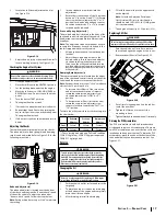
Locate the shift lever adjustment nuts (a). 

See Figure 5-18.

(a)

Figure 5-18

3. 

Adjust the nuts (a) up or down until the shift 

lever is working properly. See Figure 5-18.

Checking the Engine Start System

 WARNING

Do not allow anyone near the vehicle while testing. If the 
vehicle does not pass the test, do not operate the vehicle.

1. 

Sit on the operator’s seat. 

2. 

Place the shift lever in the NEUTRAL position.

3. 

Set the parking brake and stop the engine.

4. 

Move the shift lever to: LOW, HIGH, PARK or 

REVERSE position. Do not step on the brake 

pedal.

5. 

Turn the key to START position.

6. 

The engine should not crank.

7. 

If it cranks see an authorized service dealer.

8. 

Repeat steps 4 and 5 but when turning the 

key to start position step on the brake pedal.   

The engine should crank.

9. 

If it does not crank see an authorized service 

dealer.

Adjusting the Shocks

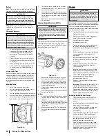
There are three adjustment points on the shocks. 

The rebound (a), pre-load spring (b) and damping 

rate (c) can be adjusted. Refer to Figure 5-19 for the 

following instructions.

C

Fa

st

Slo

w

F


   S

(a)

(b)

(c)

Figure 5-19

Rebound Adjuster (a)

The rebound adjuster is located near the bottom 

of the shock and controls the “bounce back” speed 

of the utility vehicle. To adjust the rebound or 

“bounce-back” speed,  follow the steps below:

Note: 

Each position has a stop or “click” to indicate 

the setting.

1. 

Insert a standard screw driver into the 

adjustment. 

2. 

Rotate the screw into one of the 18 positions 

between “S” (position 0) and “F” (18). Rotate 

the screw clockwise (towards the “S” or “0” 

position) to slow the rebound and counter-

clockwise (towards the “F” or “18” position) 

to speed up the rebound.

Pre-Load Spring Adjuster (b)

The pre-load adjuster is located in the body of the 

shock and controls the height of the vehicle. It can 

be adjusted to accommodate for different load 

situations.

Note: 

This adjustment requires a spanner wrench 

to complete. A spanner wrench is included in the 

tool kit shipped with this utility vehicle.
1. 

Using a spanner wrench, loosen the upper 

lock nut.

2. 

Adjust the pre-load adjuster nut to the 

desired setting. Turn the pre-load adjuster 

clockwise to increase the compression 

force (raise the utility vehicle) and turn the 

pre-load adjuster nut counter-clockwise to 

decrease the compression force (lower the 

utility vehicle).

Damping Rate Adjuster (c)

The compression adjuster is located on the upper 

part of the shock and controls the ride of the utility 

vehicle and the impact resistance of the shocks.

Note: 

Each position has a stop or “click” to indicate 

which of the 18 positions it is in.
1. 

To increase the stiffness of the suspension 

and increase the absorption of impacts, 

rotate the compression adjuster screw 

clockwise towards the “SLOW” (or “0”) 

position.

2. 

To decrease the stiffness (soften the ride) 

rotate the compression adjuster screw 

counter-clockwise towards the “FAST” (or 

“18”) position.

To return the utility vehicle to its stock setting, use 

the chart below:

Rebound 

Adjuster

Pre-Load 

Adjuster

Compression 

Adjuster

Front

Position 7

295 mm

Position 5

Rear

Position 4

300 mm 

Position 3

* -- These setting are based on a “full load” condition. 

250 lb (113 kg) driver, 250 lb (113 kg) passenger and 

500 lb (227 kg) cargo load.

Service

 WARNING

To avoid personal injury, be sure to check and service the 

vehicle on a flat surface with the engine off and the parking 

brake ON. If servicing under the cargo bed, be sure that the 

cargo bed is supported so that it can not inadvertently close. 

Do not touch muffler or exhaust pipes while they are hot; 

Otherwise, severe burns could result.

Changing the Oil

 WARNING

Be sure to stop the engine before replacing oil. Allow engine 

to cool down sufficiently, oil can be hot and can burn.

1. 

Park the vehicle on flat surface and raise the 

cargo bed.

2. 

To drain the used oil, remove the drain plug 

at the bottom of the engine and completely 

drain the oil into an oil pan.

3. 

After draining, reinstall the drain plug.

4. 

Fill with the new oil up to the upper notch 

on the dipstick.

Note: 

Oil with an American Petroleum 

Classification (API) service classification 

should be used. 10W/40SL, JASO-MA grade 

oil is recommended.

5. 

The engine oil capacity is 2.22 quarts (2.1L)

Replacing Oil Filter

 WARNING

Be sure to stop the engine before replacing oil filter. Allow 
engine to cool down sufficiently, oil can be hot and can burn.

1. 

Park the vehicle on a flat surface, remove 

the seat and open the engine access cover. 

2. 

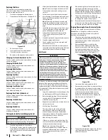
Remove the oil filter (a). See Figure 5-20.

(a)

Figure 5-20

3. 

Put a film of clean engine oil on the rubber 

seal of the new filter.

4. 

Tighten the filter until it contacts the 

mounting surface.

5. 

Tighten filter by hand an additional 1/2-turn only.

Draining the PCV Accumulator

The PCV accumulator should be drained at each 

oil changed to remove oil condensation. There are 

two PCV accumulators, one near the front of the air 

intake box and one near the rear. To drain the PCV 

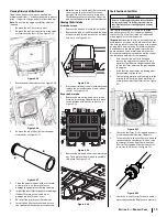
accumulator, pinch the valve at the bottom of the 

tube and allow the condensation to run out. See  

Figure 5-21.

Figure 5-21

Summary of Contents for 550 2017

Page 1: ...RESULT IN PERSONAL INJURY Operator s Manual Form No 769 13052 November 30 2017 NOTE This Operator s Manual covers several models Features may vary by model Not all features in this manual are applicab...

Page 2: ...d remove the key 21 Check overhead clearances carefully before driving under low hanging tree branches wires power lines bridges before entering or leaving buildings or in any other situation where th...

Page 3: ...ox Loading Operation 1 Do not exceed vehicle s Total Load Capacity rating of 1000 lbs 453 5 kg This includes operator passenger accessories and cargo 2 Do not exceed 500 lbs 226 7 kg load in cargo box...

Page 4: ...n result in accidents injuries or death 12 Observe proper disposal laws and regulations for gas oil etc to protect the environment 13 Prior to disposal determine the proper method to dispose of waste...

Page 5: ...eways sliding skidding or fishtailing and never do donuts Slow down before entering a turn Avoid hard acceleration when turning even from a stop Plan for hills rough terrain ruts and other changes in...

Page 6: ...time hold the ignition key on at 5 second intervals Allow the starter to rest 15 seconds between each start attempt Universal Symbols Asaguidetotheoperationofyourvehicle variousuniversalsymbolshavebee...

Page 7: ...or illustrated in this manual may not be applicable to all models We reserve the right to change product specifications designs and vehicle without notice and without incurring obligation If applicab...

Page 8: ...ide of the vehicle and are used to see behind the utility vehicle Winch N The winch is located on the front of the utility vehicle inside the bumper The winch is controlled by the winch control Occupa...

Page 9: ...ng brake Glove Box P The glove box is a small storage area in the dash on the passenger side of the utility vehicle Instrument Cluster Q The instrument cluster contains 1 Tachometer 11 DifferentialLoc...

Page 10: ...ngine will not start without the gear shift in the NEUTRAL N or PARK P position and the brake depressed 3 Insert the key into the ignition and turn it to START position Release the key when the engine...

Page 11: ...atch Lever Lift Up Cargo Bed From Here Figure 3 7 4 Once unloaded lower the cargo bed and securely latch it before operating the utility vehicle Do not drive the utility vehicle with cargo bed in the...

Page 12: ...loading ramps and equipment to safely secure the utility vehicle to the truck or trailer the only thing left to do is load it Here s how to best accomplish this task 1 Proceed with extreme caution It...

Page 13: ...ust engine valve clearance P Check fuel injection P Check injection P Change brake fluid P Replace remote hydraulic hose P Replace rear brake cylinder seal P Replace front brake cylinder seal P Flush...

Page 14: ...See Figure 5 3 When re installing the seat make sure the pins a in the seat are inserted into the holes b in the frame a a b b Figure 5 3 15 Battery light comes on when engine is running Low engine s...

Page 15: ...s a on each hinge adjust the door until an equal gap is achieved all the way around Retighten all four bolts a See Figure 5 9 a a Figure 5 9 If the door is not latching properly the latches a can be a...

Page 16: ...to see that the brake fluid level on the brake fluid reservoir a is up to the MIN b level See Figure 5 14 a c b Figure 5 14 2 If it is below the MIN b level add brake fluid but do not exceed the MAX c...

Page 17: ...er is located on the upper part of the shock and controls the ride of the utility vehicle and the impact resistance of the shocks Note Each position has a stop or click to indicate which of the 18 pos...

Page 18: ...tely Donotmixdifferenttypes ofAntifreeze Themixturecanproduceachemicalreaction betweensubstances Antifreezeisextremelyflammable andexplosiveundercertainconditions Keepfireaway fromantifreeze Keepchild...

Page 19: ...he bottom of the utility vehicle See Figure 5 29 a a a a a a a a a Figure 5 29 2 Remove the drain and allow the water to run out Then replace the drain and the middle skid plate See Figure 5 29 a Figu...

Page 20: ...ened particles out of the screen assembly and lightly clean the screen with wire brush Soak in solvent and clean with wire brush if necessary 3 If there is any damage the assembly must be replaced 4 R...

Page 21: ...ol Switch Gear Selection H L range forward Neutral Reverse Park Brakes Front Rear Wet disc brake Parking Brake Axis brake hand braking Steering Manual Electronic Power Steering Optional Dimensions Len...

Page 22: ...ons The Vehicle has been thoroughly tested for proper performance with implements sold or approved by manufacturer Use with implements which are not sold or approved and which exceed the maximum speci...

Page 23: ...Notes 7 23...

Page 24: ...24 Section 7 Notes...

Page 25: ...25 Section 7 Notes...

Page 26: ...period of two years The warranty period begins on the date the outdoor equipment is delivered to an ultimate purchaser or first placed into service Subject to certain conditions and exclusions as sta...

Page 27: ...cause of the need for repair or replacement of the part That notwithstanding any adjustment of a component that has a factory installed and properly operating adjustment limiting device is still elig...

Page 28: ...site at www mtdcanada com This limited warranty does not provide coverage in the following cases a The engine or component parts thereof These items may carry a separate manufacturer s warranty Refer...

Reviews: