15
1.
DESCRIPTION OF THE GEAR SELECTOR
SYSTEM:
1.1.
The gear selector on the 4 X 2 Utility Vehicle is
electronically controlled and vacuum actuated.
The operator selects the desired gear by push-
ing one of
three buttons on the dashboard
.
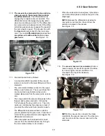
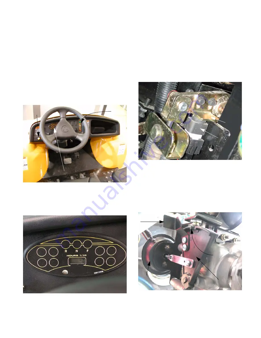
The operator engages and disengages the dif-
ferential lock using a yellow button to the left of
the steering wheel. See Figure 1.1.
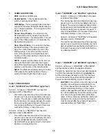
1.2.
A corresponding light on the
instrument panel
confirms the selection, or flashes a trouble code
in the event of a malfunction. See Figure 1.2.
Figure 1.1
Gear
selector
buttons
Differential
lock button
Instrument panel
Figure 1.2
Detail of the instrument panel
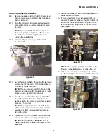
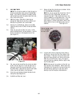
1.3.
The
brake switch
is tied into the gear selector
circuitry. The vehicle will not shift gears if the
brake pedal is not depressed far enough to actu-
ate the switch or if the switch actuator is out of
adjustment. See Figure 1.3.
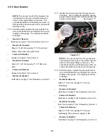
1.4.
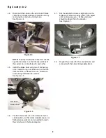
The
neutral switch
, mounted on the transaxle,
above the Shift Wedge, confirms the position of
the shift wedge. A detent in the
shift wedge
moves a contact roller in the neutral sensor
when the shift wedge moves, generating a signal
that goes to the electronic shift module (ESM).
See Figure 1.4.
Figure 1.3
Brake
switch
Adjustable
brake
switch
actuator
Figure 1.4
Shift wedge
Notch (neutral)
Manual
over-ride
Vacuum actuato
r
4 X 2 Gear Selector
Summary of Contents for BIG COUNTRY 4X2
Page 2: ......
Page 4: ......
Page 16: ...Big Country 4 x 2 12...
Page 38: ...4 X 2 Gear Selector 34...


