4 X 2 Gear Selector
29
6.3.
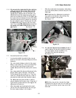
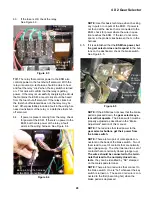
If the fuse is OK, check the relay.
See Figure 6.3.
TIP:
The relay that controls power to the ESM also
controls power to the fuel shut-off solenoid. With the
relay uncovered, a technician should be able to hear
and feel the relay “click” when the key switch is turned
on. This click will confirm that the relay is getting
power. If the relay is successfully energizing the circuit
that contains the ESM, a report click should be heard
from the fuel shut-off solenoid. If the relay clicks but
the fuel shut-off solenoid does not, the relay may be
bad. Other possibilities include a fault in the wiring har-
ness downstream of the relay, or a defective fuel shut-
off solenoid.
6.4.
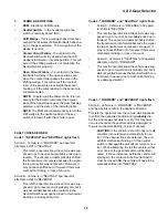
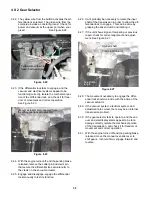
If power is present coming from the relay, check
for power at the ESM. If there is no power to the
ESM, but there is power at the relay, a fault
exists in the wiring harness. See Figure 6.4.
Figure 6.3
Key to relay
center
removed
with covers
Relay center
Figure 6.4
Back-probing the harness
at the ESM connection
NOTE:
Use this basic technique when checking
any in-puts or out-puts of the ESM. If power is
not found at the device that is connected to the
ESM, check for power where the wire in ques-
tion reaches the ESM. If the two do not corre-
spond, a the problem lies between them, in the
harness.
6.5.
If it is established that the
ESM has power, but
the gear selector does not respond
to the but-
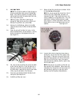
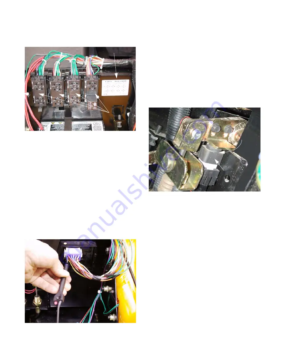
tons on the dashboard, check the brake switch.
See Figure 6.5.
NOTE:
If the ESM does not know that the brake
pedal is pressed down, the
gear selector sys-
tem will not operate
. The brake switch must be
properly adjusted as described in the “Brake
Adjustment” section of this manual.
NOTE:
The red wires that feed power to the
gear selector buttons get their power from
the brake switch.
NOTE:
There are two pair of male spade con-
nectors on the back of the brake switch. Two of
them lead to a set of contacts that are normally
open (plunger up). The other two lead to a set of
contacts that are normally closed (plunger up).
The wires should be connected to the termi-
nals that lead to the normally closed con-
tacts.
they can be identified by “NC” stamped
on the male spade terminal.
NOTE:
There are two red wires that connect to
the brake switch. One is “hot” whenever the key
switch is turned on. The second red wire is con-
nected to the first (becoming hot) when the
brake pedal is depressed.
Figure 6.5
(normally open)
Brake switch
Plunger
down:
contacts
closed
Summary of Contents for BIG COUNTRY 4X2
Page 2: ......
Page 4: ......
Page 16: ...Big Country 4 x 2 12...
Page 38: ...4 X 2 Gear Selector 34...


