RZT-S Zero
134
Leveling the deck
For the best quality cut, the deck must be level side to side and the front of the deck should be 1/4” lower than
the rear of the deck.
To level the deck:
NOTE:
Deck leveling is part of initial mower setup. Before adjusting an out of level deck on a mower that has
been used, inspect all of the deck lift and suspension linkages. Move the deck through its full range of
travel while checking linkage movement. Repair any damaged or binding linkage before leveling the
deck.
NOTE:
Check the mower’s tire pressure before performing any deck leveling adjustments. The recommended
operating tire pressure is:
•
Approximately 10 psi for the rear tires
•
Approximately 20 psi for the front tires
NOTE:
When either deck level or pitch are adjusted, check both level and pitch after the adjustment has been
made.
Side to Side Leveling
NOTE:
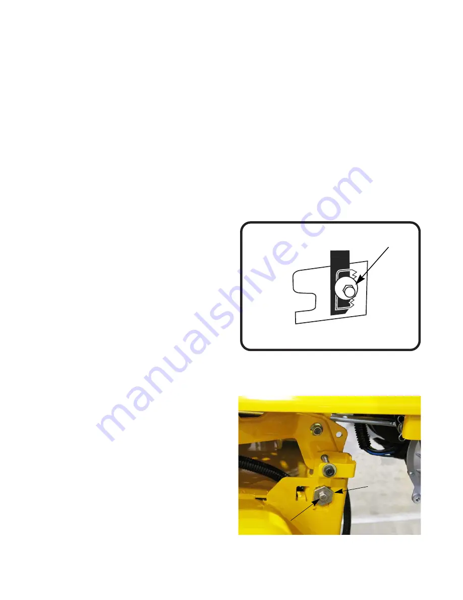
When leveling the deck side-to-side, make
sure the two rear adjustment gears are set in
the middle of the adjustment range.
See Figure 7.11.
1.
With the mower parked on a firm, level surface,
move the deck to the mid height or most commonly
used position using the deck lift lever. Rotate the
blades so that they are perpendicular with the
mower frame.
2.
Measure the distance from the outside of the left
blade tip to the ground and the distance from the
outside of the right blade tip to the ground. Both
measurements taken should be equal. If they are
not, note whether the left side of the deck is lower or
higher and proceed to the next step.
3.
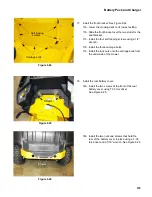
Loosen, but do NOT remove, the hex bolt on the
front left deck hanger link. See Figure 7.12.
NOTE:
The front right deck hanger link is not adjust-
able
4.
To level the deck turn the adjustment gear, located
immediately behind the bolt. Turn the gear clock-
wise (rearward) to raise the left side of the deck.
Turn the gear counter-clockwise (toward front) to
lower the left side of the deck. See Figure 7.12.
5.
The deck is properly leveled when both blade tip
height measurements, as described earlier, are
equal.
6.
Tighten the bolt on the left deck hanger bracket
when proper adjustment is achieved.
Figure 7.11
adjustment gear
Figure 7.12
Adjustment
gear
Loosen bolt
Summary of Contents for RZT-S Zero
Page 2: ......
Page 42: ...RZT S Zero 38 ...
Page 112: ...RZT S Zero 108 ...
Page 154: ...NOTES ...
Page 155: ......
Page 156: ...MTD Products Inc Product Training and Education Department FORM NUMBER 769 08008 02 05 2013 ...


