Body
13
Seat box assembly
The RZT-S Zero has a bolt together seat box assembly. The individual parts of the seat box are serviced sepa-
rately, not as one complete assembly. This section will be divided into three sections to cover the service procedures
for the three main parts of the seat box assembly.
Seat box top plate
The seat box top plate will need to be removed to perform service procedures such as:
•
Removing the deck
•
Replacing the slotted deck lift links
•
Replacing the deck lift shaft brackets
•
Removing the deck motors
•
Removing the hub motors
To remove/replace the seat box top plate:
1. Disconnect the battery pack’s positive lead from the
contactor assembly by following the procedures
described in the left pod section of this chapter.
2.
Remove the rear battery cover by following the pro-
cedures described in Chapter 6: Battery Pack and
Charger.
3.
Remove the left and right pods by following the pro-
cedures described earlier sections of this chapter.
4.
Disconnect the seat switch
5.
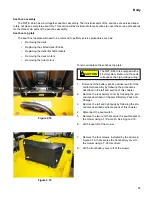
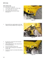
Remove the two nuts that secure the seat bracket to
the mower using a 1/2” wrench. See Figure 2.18.
6.
Lift the seat off of the mower.
7.
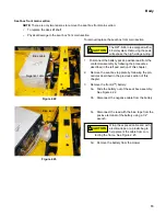
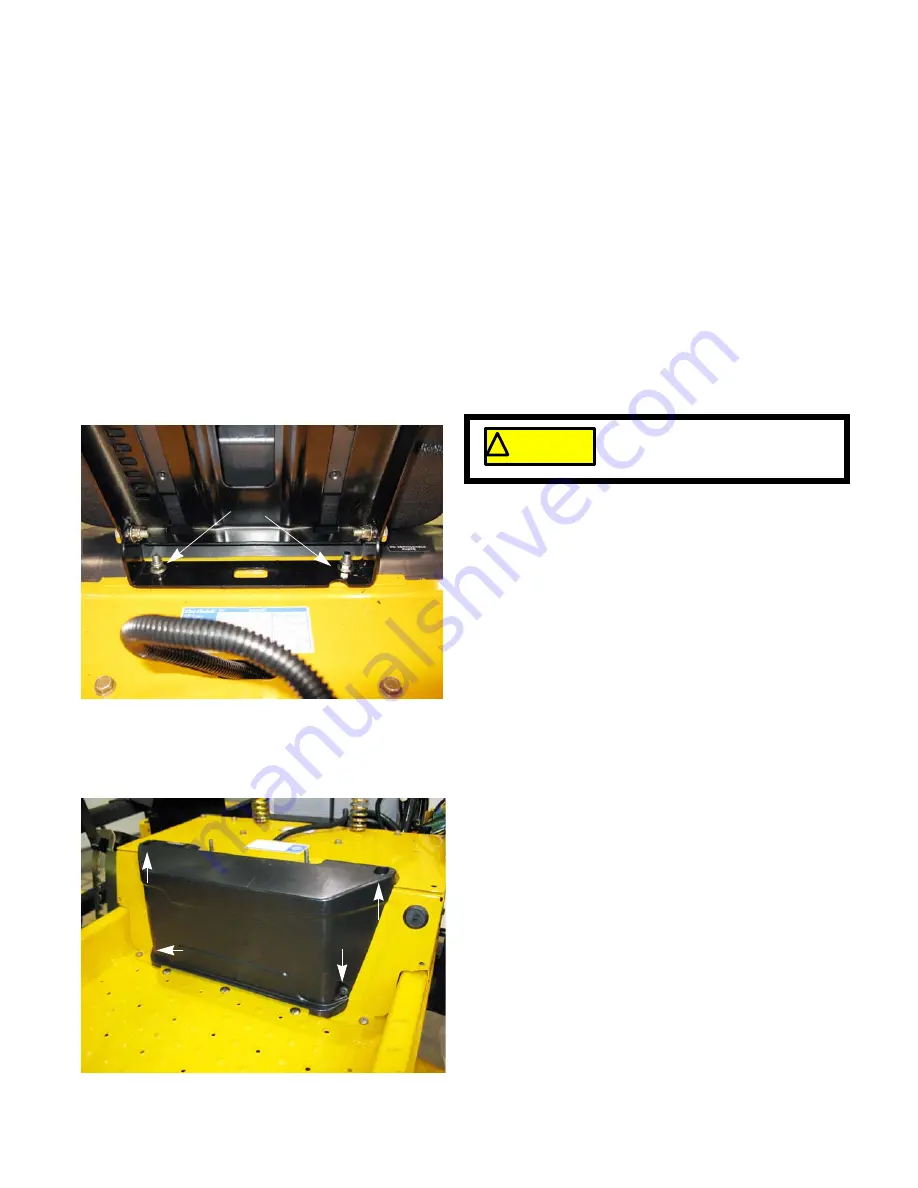
Remove the four screws, indicated by the arrows in
Figure 2.19, that secures the front battery cover to
the mower using a T-30 torx driver.
8.
Lift the front battery cover off of the mower.
Figure 2.18
Battery
Nuts
! CAUTION
! CAUTION
The RZT-S Zero is equipped with a
48 volt system. Removing the pods
will expose the high voltage wiring.
Figure 2.19
Summary of Contents for RZT-S Zero
Page 2: ......
Page 42: ...RZT S Zero 38 ...
Page 112: ...RZT S Zero 108 ...
Page 154: ...NOTES ...
Page 155: ......
Page 156: ...MTD Products Inc Product Training and Education Department FORM NUMBER 769 08008 02 05 2013 ...


