RZT-S Zero
40
6.
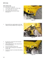
Install a 1/4” alignment pin in the left segment gear.
See Figure 4.2.
7.
Install a 1/4” alignment pin in the right segment
gear.
8.
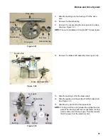
Remove the axle casting covers.
9.
Insert the axle casting (5/16”) alignment pins into
the alignment holes in both axle castings.
See Figure 4.3.
10.
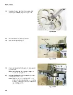
Adjust the ball joints on the threaded drag links to
align them with the holes in the segment gears.
See Figure 4.4.
11.
Install the nuts and bolts that attach the drag links to
the segment gears.
12.
Tighten the drag link ball joint jam nuts.
13.
Remove all of the alignment pins.
14.
Install the axle casting covers.
15.
Install the floor pan, following the procedures
described in Chapter 2: Body.
16.
Test drive the mower in a safe area before returning
it to service.
NOTE:
Do not put a mower back into service if it
does not react properly to control inputs.
Figure 4.2
1/4” Alignment pin
Figure 4.3
Alignment pin
Figure 4.4
Holes aligned
Summary of Contents for RZT-S Zero
Page 2: ......
Page 42: ...RZT S Zero 38 ...
Page 112: ...RZT S Zero 108 ...
Page 154: ...NOTES ...
Page 155: ......
Page 156: ...MTD Products Inc Product Training and Education Department FORM NUMBER 769 08008 02 05 2013 ...


