Electrical System
69
7.
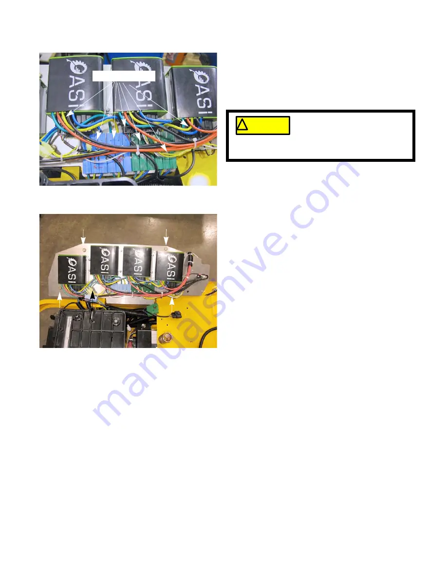
Disconnect the motor harness connectors.
See Figure 5.23.
NOTE:
Do not disconnect the five wires that go under the
controller cover.
NOTE:
Do not disconnect the harness that runs from the
contactor assembly to the controllers. It is serviced
as part of the control panel.
8.
Remove the five screws that hold the control panel to
the mower using a 1/2” wrench. See Figure 5.24.
9.
Lift the control panel off of the mower.
10.
Install the control panel by following the previous
steps in reverse order.
Figure 5.23
Motor connectors
! CAUTION
! CAUTION
Do not remove the controller cov-
ers. There are pre-charge capaci-
tors in the controllers. These
capacitors will hold a charge after the harnesses
are disconnected.
Figure 5.24
Summary of Contents for RZT-S Zero
Page 2: ......
Page 42: ...RZT S Zero 38 ...
Page 112: ...RZT S Zero 108 ...
Page 154: ...NOTES ...
Page 155: ......
Page 156: ...MTD Products Inc Product Training and Education Department FORM NUMBER 769 08008 02 05 2013 ...


