background image

16

1

2

3

4

5

6

2

7

8

9

10

11

12

13

14

15

16

50

54

19

20

21

22

23

24

25

26

27

28

29

30

31

32

33

34

35

36

37

38

39

40

41

42

30

37

30

43

27

23

46

47

48

49

55

56

56

Summary of Contents for Series 390

Page 1: ...ed in effective working order by the operator In the State of California the above is required by law Section 4442 of the California Public Resources Code Other states may have similar laws Federal laws apply on federal lands A spark arrester for the muffler is available through your nearest engine authorized service dealer or contact the service department P O Box 361131 Cleveland Ohio 44136 0019...

Page 2: ...rmation to the sample model plate provided to the right You can locate the model plate by looking at the rear of the tine shield This information is important for use when visiting the manufacturer s web site obtaining assistance from the Customer Support Department or when communicating with an authorized service dealer If you have difficulty assembling this product or have any questions regardin...

Page 3: ... Safety Labels Found On Your Tiller 1 Safety Labels WARNING DO NOT remove safety or any labels from tiller for any reason ...

Page 4: ...d into neutral N before starting the engine Never leave this machine unattended with the engine running Never attempt to make any adjustments while engine is running except where specifically recommended in the operator s manual To avoid personal injury or property damage use extreme care in handling gasoline Gasoline is extremely flammable and the vapors are explosive Serious personal injury can ...

Page 5: ... this power machine to persons who read understand and follow the warnings and instructions in this manual and on the machine The safety labels on the tiller are shown in the Safety Labels section To ensure safe operation of the tiller follow the instructions on all labels closely After striking a foreign object stop the engine disconnect the spark plug wire and ground against the engine Thoroughl...

Page 6: ... handle into frame Figure 3 2 Insert cables into levers Be sure not to kink cables while attaching 2 Hook the Z end of the forward clutch cable A into the forward tine engagement lever Figure 3 2 3 Hook the Z end of the reverse clutch cable B into the reverse tine engagement lever Figure 3 2 4 Remove the hex bolt and cupped washer from the right side of the frame Hold the cable guide bracket on th...

Page 7: ...ed position Figure 3 4 Return to lower handle and tighten the hex bolt securely Depth Gage Attachment 1 Disassemble the depth gage assembly as seen in Figure 3 5 Retain the pin and clip for later reassembly Figure 3 5 Disassemble depth gage if necessary Figure 3 6 Insert depth gage bracket into frame Figure 3 7 Reassemble depth stake 2 Remove the two screws from the rear of the tiller frame as sho...

Page 8: ...Never engage both the forward and reverse tine drives at the same time Engaging both forward and reverse tine drives at the same time could damage the belt drives and cause the engin to stall Depth Stake The depth stake controls the tilling depth Refert to Operating Your Tiller later in this section for further instructions on its use Tines and End Caps Tilling tines and end caps are used to culti...

Page 9: ...e sure no one is standing in front of the tiller while the engine is running or being started Refer to the engine manual for instructions 1 Attach spark plug wire to spark plug Make sure the metal cap on the end of the spark plug is fastened securely over the metal tip on the spark plug 2 Make sure that the tine clutch control is disengaged Operating Your Tiller 3 Move throttle control 1 3 of the ...

Page 10: ...s for shallow tilling cultivating and transport See Figure 4 4 Yoke to Back Place the wheel yoke so that wheels are toward rear closest to depth stake for deep tilling and cultivating See Figure 4 5 Depth Stake The depth stake acts as a brake for the tiller and controls the depth and speed at which the machine will operate Remove the clevis pin and hairpin clip to raise or lower depth stake See Fi...

Page 11: ...eing Figure 4 10 The tiller has many uses other than tilling and cultivating a garden One of these is the preparation of lawn area for seeding The tiller will prepare a deep seed bed which will be free of hard untilled spots allowing a better stand of grass to grow The tiller is very useful for loosening hard soil for excavation with a shovel No tedious handwork will be necessary Your tiller may b...

Page 12: ... It should not be replaced with an off the shelf belt Order all belts through you authorized service dealer 1 Disconnect and ground the spark plug wire against the engine 2 Remove the belt cover from the left side of the tiller by removing the two self tapping screws and hex stop nut and washer See Figure 5 1 3 Remove belt from transmission pulley and then from around the reverse idler pulley See ...

Page 13: ...ure 5 4 4 The forward idler belt will not clear the belt keepers near the engine pulley You must remove the reverse idler bracket to allow the belt to move off of the engine pulley Remove the two securing screws and move the bracket toward the transmission pulley Retain the screws for reassembly See Figure 5 5 5 Remove belt from the reverse idler pulley and then from around the transmission pulley...

Page 14: ...ghten the lock nut against the cable collar See Figure 5 10 5 With the forward and reverse tine engagement handles in neutral released positions pull the starter rope several times The tines should not turn If they turn forward adjust the forward tine engagement cable to release tension using the previous steps in this section If the tines turn toward rear adjust the reverse tine engagement cable ...

Page 15: ...th proper oil Refer to the engine manual packed with your unit Refer to the engine manual packed with your unit Adjust carburetor as instructed in separate engine manual Tines do not engage Foreign object lodged in tines Tine clevis pin s missing Pulley and idler not in correct adjustment Not shifting properly Control cable not adjusted properly Belt worn and or stretched Dislodge foreign object R...

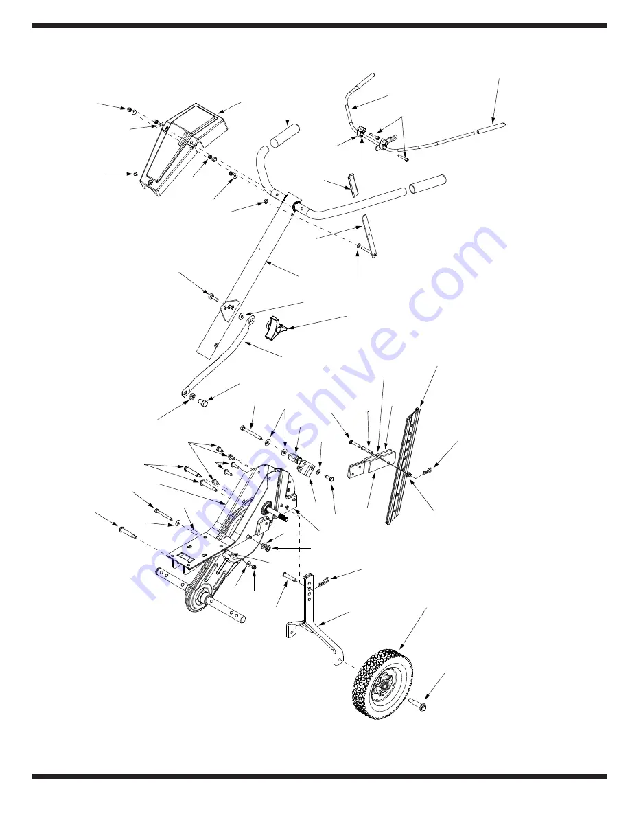
Page 16: ...16 1 2 3 4 5 6 2 7 8 9 10 11 12 13 14 15 16 50 54 19 20 21 22 23 24 25 26 27 28 29 30 31 32 33 34 35 36 37 38 39 40 41 42 30 37 30 43 27 23 46 47 48 49 55 56 56 ...

Page 17: ...0004 Tail Piece Bracket R H 27 711 0415 Clevis Pin Ref Part No Part Description 28 710 0805 Hex Bolt 5 16 18 x 1 5 Lg 29 710 0189 Hex Bolt 5 16 18 x 3 Lg 30 736 0242 Wash Bell 340 I D x 872 O D 31 711 1036A Spec Hex Nut 32 736 0119 L Wash 5 16 I D 33 710 3008 Hex Bolt 5 16 18 Gr 5 34 786 0129 Cable Guide Bracket 35 710 0604A Hex Washer Screw 5 16 18 x 62 Lg 36 710 0602 Hex Wash Hd TT Tap Scr 37 73...

Page 18: ...18 3 17 18 21 19 16 43 44 46 47 4 5 7 11 2 1 6 8 9 10 5 14 45 38 7 22 6 42 36 10 33 3 13 30 29 32 31 34 35 28 27 49 48 25 26 24 24 23 20 50 51 10 Honda Engine 52 54 53 ...

Page 19: ... 0585 Fl Pulley 6 Dia 25 750 0892 Spacer 64 Dia x 2 4 Lg Ref Part No Part Description 26 748 0350 Pulley Mounting Adapter 27 736 0112 Bell Wash 525 I D x 1 5 O D 28 712 3029 Hex Jam Nut 1 2 20 Thd 29 732 0697 Return Spring 30 786 0040B Reverse Bracket 31 736 0119 Lock Washer 5 16 32 710 0237 Hex Bolt 5 16 24 x 625 33 756 0971 Engine Inner Half Pulley 34 756 0600 Reverse Engine Pulley 35 736 0452 B...

Page 20: ...rior finish due to use or exposure d Cub Cadet does not extend any warranty for products sold or exported outside of the United States its possessions and territories except those sold through Cub Cadet s authorized channels of export distribu tion e Replacement parts that are not genuine Cub Cadet parts f Service completed by someone other than an authorized service dealer g Transportation charge...

Reviews: