background image

S

ection

 5— o

peration

22

Driving the Tractor Forward 

WARNING! 

Keep all movement of the drive pedals 

slow and smooth. Abrupt movement of the pedals 

can affect the stability of the tractor and could cause 

the tractor to flip over, which may result in serious 

injury or death to the operator.

1. 

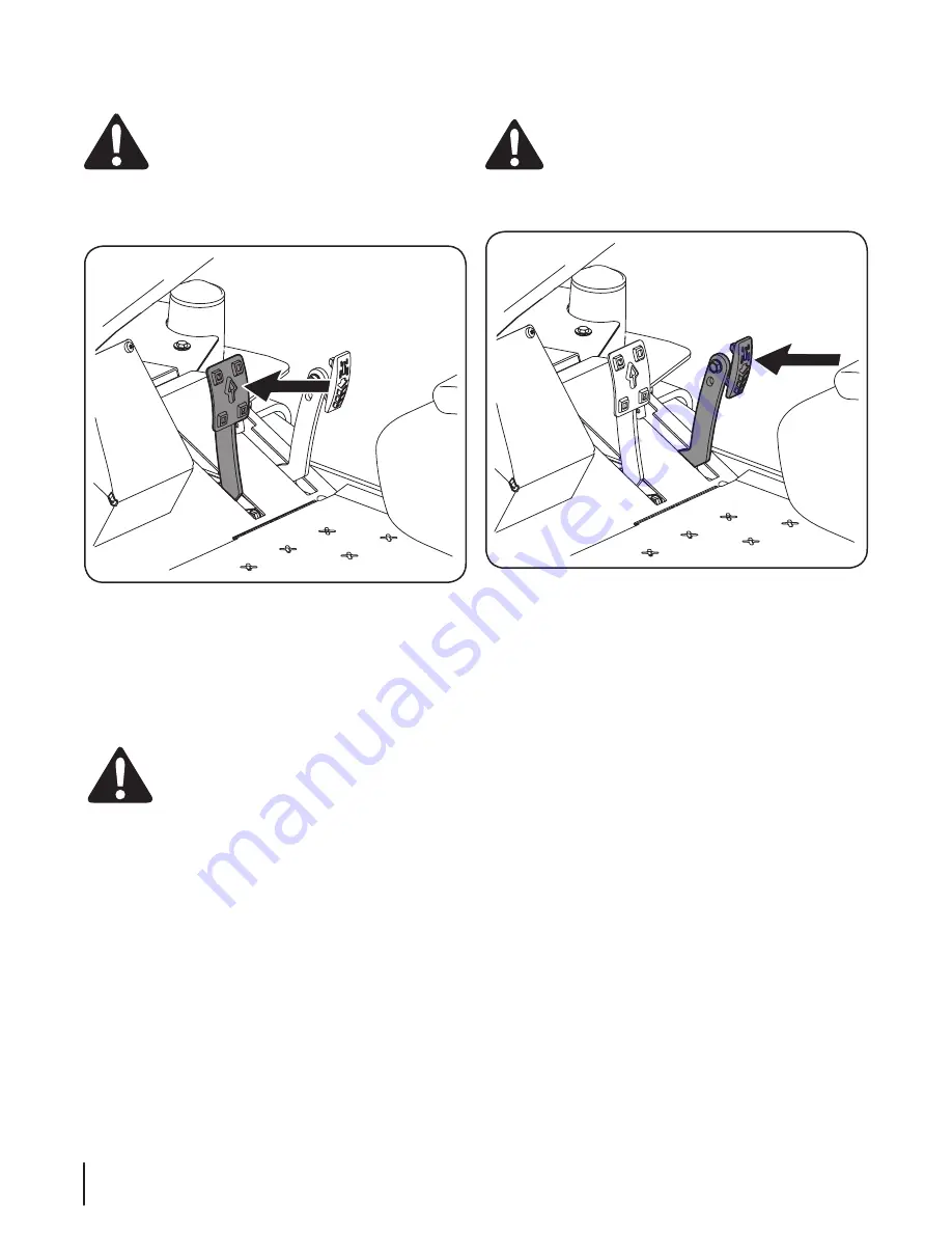
Slowly push the forward drive pedal forward. The tractor 

will start to move forward. See Figure 5-1.

Figure 5-1

2. 

As the forward drive pedal is pushed farther forward the 

speed of the tractor will increase.

3. 

To slow the tractor, slowly release the forward drive pedal 

to attain the desired speed, or allow to pedal to return the 

neutral position to stop the tractor.

Turning the Tractor While Driving Forward

WARNING! 

When reversing the direction of travel, 

we recommend performing gradual ‘U’ turns where 

possible. Sharper turns increase the possibility of turf 

defacement, and could affect control of the tractor. 

ALWAYS slow the tractor before making sharp turns.

To turn the tractor while driving forward, use the steering wheel 

to turn in the direction you wish to travel. 

1. 

To turn to the left, turn the steering wheel counter-

clockwise (to the operator’s left).

2. 

To turn to the right, turn the steering wheel clockwise (to 

the operator’s right). 

3. 

The greater the distance the steering wheel is turned, the 

sharper the tractor will turn.

4. 

To execute a “pivot turn,” move the steering wheel so that 

the inside wheel is angled at approximately 88 degrees and 

the turn side tire will not rotate.

NOTE: 

Making a “pivot turn” on grass will greatly increase 

the potential for defacement of the turf as well as potential 

damages to the traction surface and the tire.

Driving the Tractor In Reverse

WARNING! 

Always look behind and down on both 

sides of the tractor before backing up. Always look 

behind while traveling in the reverse direction.

1. 

Slowly push the reverse drive pedal forward. The tractor 

will start to move in the reverse direction. See Figure 5-2.

Figure 5-2

2. 

As the reverse drive pedal is pushed farther forward the 

speed of the tractor will increase.

3. 

To slow the tractor release the reverse drive pedal to attain 

the desired speed, or allow the pedal to return to the 

neutral position to stop the tractor.

Turning While Driving Rearward

To turn the tractor while driving rearward, use the steering wheel 

to turn in the direction you wish to travel. 

1. 

To turn to the left while traveling in reverse, turn the 

steering wheel clockwise (to the operator’s right). 

2. 

To turn to the right while traveling in reverse, turn the 

steering wheel counter-clockwise.

3. 

The greater the distance the steering wheel is turned, the 

sharper the tractor will turn.

4. 

To execute a “pivot turn,” move the steering wheel so that 

the inside wheel is angled at approximately 88 degrees and 

the turn side tire will not rotate. 

NOTE: 

Making a “pivot turn” on grass will greatly increase 

the potential for defacement of the turf as well as potential 

damages to the traction surface and the tire.

Summary of Contents for TANK SZ 54

Page 1: ... Practices Set Up Operation Maintenance Service Troubleshooting Warranty WARNING READ AND FOLLOW ALL SAFETY RULES AND INSTRUCTIONS IN THIS MANUAL BEFORE ATTEMPTING TO OPERATE THIS MACHINE FAILURE TO COMPLY WITH THESE INSTRUCTIONS MAY RESULT IN PERSONAL INJURY Form No 769 09314 September 10 2013 Tank SZ ...

Page 2: ...self with the machine its features and operation Please be aware that this Operator s Manual may cover a range of product specifications for various models Characteristics and features discussed and or illustrated in this manual may not be applicable to all models We reserve the right to change product specifications designs and equipment without notice and without incurring obligation If applicab...

Page 3: ...io 44136 0019 This spark ignition system complies with Canadian ICES 002 DANGER The engine manufacturer has supplied an engine owner s manual for information regarding US Environmental Protection Agency EPA and California Air resources Board CARB regulations relating to emission control systems maintenance and warranty Making any unauthorized alterations or modifications to the engine fuel or vent...

Page 4: ...aining this machine Long hair loose fitting clothing or jewelry may get entangled in moving parts Follow all federal state and local guidelines regarding the use of personal protective equipment 10 Be aware of the mower and attachment discharge direction and do not point it at anyone Do not operate the mower without the discharge cover or entire grass catcher in its proper place 11 Do not put hand...

Page 5: ...terrain could overturn the machine Tall grass can hide obstacles 3 Use slow speed Choose a low enough speed so that you will not have to stop while on the slope Avoid starting or stopping on a slope If the tires are unable to maintain traction disengage the blades and proceed slowly and carefully straight down the slope 4 Keep all movements on the slopes slow and gradual Do not make sudden changes...

Page 6: ... except when the ROPS are a Not properly installed and or not properly secured onto the machine b Damaged in such manner that their structural integrity has been compromised c Not in their fully upright and locked position 4 Seat belts are attached to the movable portion of the seat when suspension seats are utilized and therefore the seat mounting base must be secured to its pivot means and the p...

Page 7: ...el cap or add fuel while the engine is hot or running Allow engine to cool at least two minutes before refueling h Never over fill fuel tank Fill tank to no more than inch below bottom of filler neck to allow space for expansion i If necessary use a funnel to avoid spillage j Replace fuel cap and tighten securely k If fuel is spilled wipe off the engine and equipment Wait 5 minutes before starting...

Page 8: ...ay Tampering with the governor setting can lead to a runaway engine and cause it to operate at unsafe speeds Never tamper with factory setting of engine governor Notice Regarding Emissions This machine is equipped with an engine that is certified to federal EPA emission standards for non road engines and equipment and where applicable to California Air Resources Board CARB emission standards The e...

Page 9: ...p and throw objects which can cause serious personal injury BYSTANDERS Keep bystanders helpers children and pets at least 75 feet from the machine while it is in operation MAX 20 WARNING SLOPE OPERATION Do not operate this machine on a slope greater than 20 degrees DANGER ROTATING BLADES To reduce the risk of injury keep hands and feet away Do not operate unless discharge cover or grass catcher is...

Page 10: ...ee Figure 1 and Figure 2 4 Adjust gauge up or down until the left corner touches the slope See Figure 1 and Figure 2 5 If there is a gap below the gauge the slope is too steep for safe operation See Figure 2 above 2 0 d a s h e d l i n e Slope Gauge Figure 2 Figure 1 20 Slope 20 Slope WARNING Slopes are a major factor related to tip over and roll over accidents which can result in severe injury or...

Page 11: ...m yours NOTE All references in this manual to the left or right side and front or back of the machine are from the operating position only Exceptions if any will be specified Tractor Preparation TOOLSNEEDED Safety glasses leather gloves wire cutters 1 Remove the upper crating material from the shipping pallet and cut any bands or tie straps securing the tractor to the pallet 2 Use the deck lift pe...

Page 12: ...stem nozzle adapter from the manual bag and store for future use Cut the wire tie holding the chute deflector up and discard any packing material Install Roll Over Protective System ROPS The Roll Over Protective System ROPS has not been installed on your unit for shipping purposes Using the hardware found in the Roll Over Protective System container install it on your unit as follows 1 Insert each...

Page 13: ...anyard as shown in Figure 3 6 Be sure to secure the lanyard to the retaining clip and clevis pin A B C Figure 3 6 8 Move the upper ROPS section to the upright position and insert the locking pins with their retainer hairpin clips See Figure 3 7 Locking Pin Locking Pin Retainer Hairpin Clips Figure 3 7 Steering Wheel Column The steering wheel column is tilted all the way back for shipping purposes ...

Page 14: ... the seat see below In the neutral position with hands on the steering wheel Operator s upper arms should be relaxed and approximately vertical Operator s forearms should be approximately horizontal Operator s back should stay in contact with the seat back Steering column should not contact operator s legs Check the results of any adjustments to the conditions described above Repeat any adjustment...

Page 15: ...to the left and slide the seat forward or back into the desired position and release the rod when the seat is in the desired position See Figure 3 13 Figure 3 13 The mechanical suspension mechanism incorporates weight ride adjustment controls for operators in the 100 to 280 lb weight range turn the knob on the front of the seat clockwise to increase the weight capacity and counter clockwise to dec...

Page 16: ...on the back of the seat frame lift up on the lever and tilt the seat forward locking it in place with the seat prop NOTE The positive battery terminal is marked Pos The negative battery terminal is marked Neg NOTE If the positive battery cable is already attached skip ahead to step 2 2 Remove the red boot if present from the positive battery terminal and attach the red cable to the positive batter...

Page 17: ...e key from the ignition switch when the tractor is not in use Power Take Off PTO Knob The PTO knob is located on the LH console to the left of the operator s seat next to the ignition switch The PTO knob operates the electric PTO clutch mounted on the bottom of the engine crankshaft Pull the knob upward to engage the PTO clutch or push the knob downward to disengage the clutch The PTO knob must be...

Page 18: ...ard drive pedal forward to cause the tractor to travel forward Ground speed is also controlled with the forward drive pedal The further forward the pedal is pivoted the faster the tractor will travel The pedal will return to its original neutral position when it s not pressed Reverse Drive Pedal The reverse drive pedal is located on the right side of the tractor along the running board Ground spee...

Page 19: ...nsmission oil that occurs as the transmission warms up during operation DO NOT FILL THE RESERVOIR Under normal operating conditions no oil should be added to the reservoir The COLD oil level should be approximately 1 4 above the bottom of the reservoir NOTE Prior to the initial operation of the tractor the oil level in the reservoir may be slightly higher than the maximum due to air in the oil lin...

Page 20: ...perator If the interlock system should ever malfunction do not operate the machine Contact your authorized Cub Cadet Dealer The safety interlock system prevents the engine from cranking or starting unless the speed control pedals are in the neutral position the parking brake is engaged and the PTO knob is disengaged To avoid sudden movement when disengaging the parking brake the safety interlock s...

Page 21: ...ation Initial Use Operating a zero turn tractor is not like operating a conventional type riding tractor Although and because a zero turn tractor is more maneuverable getting used to operating the speed control pedals and the steering wheel takes some practice It is strongly recommend that you locate a reasonably large level and open practice area where there are no obstructions pedestrians or ani...

Page 22: ...o that the inside wheel is angled at approximately 88 degrees and the turn side tire will not rotate NOTE Making a pivot turn on grass will greatly increase the potential for defacement of the turf as well as potential damages to the traction surface and the tire Driving the Tractor In Reverse WARNING Always look behind and down on both sides of the tractor before backing up Always look behind whi...

Page 23: ...ob Operate the PTO knob as follows 1 Move the throttle control lever to approximately the mid throttle position 2 Pull the PTO knob switch upward to the ENGAGED position 3 Advance the throttle lever to the operating speed full engine speed 4 The operator must remain in the tractor seat at all times If the operator should leave the seat without turning off the power take off switch the tractor s en...

Page 24: ...e are generally the best cutting blades for most grasses and mowing conditions These blades will provide extra lift for the thinner leaf grasses will handle lush grasses and will provide maximum grass and debris discharge These blades are generally required for material collection systems More horsepower is required for these blades when compared to others and they generally produce the highest no...

Page 25: ...2 1 2 Low 3 to 5 High 1 to 2 1 2 Low 3 to 5 Wet Installed Installed Hi lift High 1 to 2 1 2 Low 3 to 5 High 1 to 2 1 2 Low 3 to 5 High 1 to 2 1 2 Low 3 to 5 Table Notes This table is a general outline of suggested settings mowing conditions may vary Inner Baffle The inner baffle regulates grass discharge Remove the inner baffle for high volume grass and install the inner baffle for precision cutti...

Page 26: ... fluid level in transmission oil expansion reservoir P Check engine intake screen cover P Clean mower P Blow out clean the pump control area under floor pan P Blow out clean the pedal control area under the foot rest P Lubricate wear points see chart P P Grease three spindle bearings P Clean engine cooling fins external surfaces P Lubricate all grease fittings see chart P Change hydrostatic fluid ...

Page 27: ...ual for other approved options Hydrostatic Fluid Cub Drive System Fluid Plus Shell TT SB Castrol Syntec Edge 5W50 Number of Grease Fittings Description EVERY 25 HOURS 3 Blade Spindle Bearings WEEKLY 2 Front Wheels 2 Front Wheel Spindles 2 Mower Deck Ball Wheels Number of Grease Points Description WEEKLY 2 Deck Take Up Idler Pivots 1 Axle Pivot 1 Hydro Take up Idler Pivot LUBRICATION CHART Use a gr...

Page 28: ...g done at owner s expense may be performed by any engine repair establishment or individual WarrantyrepairsmustbeperformedbyaCubCadetDealer Changing the Engine Oil WARNING If the engine has been recently run the engine muffler and surrounding metal surfaces will be hot and can cause burns to the skin Exercise caution to avoid burns Maintain oil level as instructed in engine manual Be careful not t...

Page 29: ...e tire Balance inflation pressure between the rear tires to help maintain straight travel see tire side wall for proper pressure Keep the valve caps tightened to prevent air pressure loss Inflation Pressure Rear Tires 10 12 psi Front Tires 20 25 psi Leaking Tires When a flat tire occurs repair or replace immediately The normal procedure is to remove the wheel and replace it If a tire is getting so...

Page 30: ...tery to prevent possible discharge Recharge the battery periodically when in storage NOTE Remove the battery if exposed to prolonged periods of sub freezing temperatures Store in a cool dry location where temperatures are above freezing 8 Lubricate all lubrication points 9 Inspect the hydraulic hoses lines and fittings Replace as necessary 10 Jack the mower up and store it on blocks to take the we...

Page 31: ... left to take the slack out of the threaded rod 6 Tighten both lower jam nuts to secure the deck adjustment 7 The final adjustment would be to take the slack out of the left rear linkage if the rear of the deck was raised by adjusting the jam nuts on the eyebolt Loosen the jam nuts and tighten the upper nut to remove slack In many cases it will be necessary to adjust deck height using both eyebolt...

Page 32: ...s not hold See Figure 6 4 Brake Shoes The brake shoes can be adjusted as the shoes wear To adjust the brake shoes proceed as follows NOTE If the brakes need replaced please see your Cub Cadet Service Dealer 1 There is an access hole on the lower inside of the backing plate inside the rear tires Locate this hole and remove the rubber plug to access the adjusting star on the brake shoes See Figure 6...

Page 33: ... the drum See Figure 6 6 5 Repeat the procedure for the opposite brake shoe Removing Installing the Inner Baffle The inner flow control baffle can be removed depending on the mowing conditions The baffle controls discharge and can be removed for high volume grasses and installed for precision cutting 1 Remove the carriage bolts push nuts and flange lock nuts that secure the baffle to the deck to m...

Page 34: ... two fuses located inside the left console Lift the seat and look down at the left console to find the location of the fuses One 30 amp fuse for the power steering and one 25 amp fuse the ignition PTO etc These are standard plug in type automotive fuses Always use the same capacity fuse for replacement Check the 30 amp fuse if the power steering is not working and check the 25 amp fuse for all oth...

Page 35: ...se extreme caution when near the muffler Allow the muffler to fully cool before removing the belt from the PTO pulley 4 Using a 1 2 drive in the idler pulley bracket turn the wrench towards the right of the tractor and slide the belt off the PTO pulley See Figure 7 2 Idler Pulley Bracket PTO Belt PTO Belt Idler Pulley Bracket 60 Deck 48 Deck Figure 7 2 5 Remove the four lynch pins that secure the ...

Page 36: ...h spark plug caps 2 Remove the PTO belt refer to Deck Removal on page 34 3 Pull the four latches up and rotate 1 4 turn to line up with the slots in the deck covers and remove both covers See Figure 7 6 Figure 7 6 4 Using a 1 2 drive insert the male end into the 1 2 square opening in the deck idler assembly and rotate the idler clockwise See Figure 7 7 While holding the deck idler loosen the deck ...

Page 37: ... the deck housing See Figure 7 8 Block of Wood Figure 7 8 4 Use a 1 1 8 socket wrench on the pulley side of the spindle bolt See Figure 7 9 Flange Lock Nut Blade Hex Screw Figure 7 9 5 Remove the hex nut at the blade using a 1 1 8 wrench and remove the blade 6 To replace the blade reverse the above process and tighten nut to 100 120 lb ft NOTE When replacing the blade be sure to install the blade ...

Page 38: ...rating position WARNING Use a torque wrench to tighten the blade spindle hex flange nut to between 100 lbs ft and 120 lbs ft Changing the Spindle Assembly 1 Remove the deck as instructed in the Deck Removal section 2 Jack up the front of the mowing deck about one foot and block it in that position 3 Remove the deck cover 4 Remove the drive belts See Replacing the Deck belt 5 Remove the blade See R...

Page 39: ...ressure 1 Perform side to side deck adjustment 2 Sharpen or replace blade 3 Check tire pressure in all four tires Mower will not mulch grass If Equipped w Mulching Kit 1 Engine speed too low 2 Wet grass 3 Excessively high grass 4 Dull blade 1 Place throttle in FAST rabbit position 2 Do not mulch when grass is wet 3 Mow once at a high cutting height then mow again at desired height or make a narrow...

Page 40: ...942 04416 Hi Lift Blade 19 0 SZ 54 942 04415 Hi Lift Blade 21 0 SZ 60 918 05132 Deck Spindle 634 3159 Deck Wheel 731 09783 Deck Skid Guard 925 1707D Battery 751 12754 Gas Cap Contact your Cub Cadet dealer to order replacement parts or a complete Parts Manual have your full model number and serial number ready Parts Manual downloads are also available free of charge at www cubcadet com ...

Page 41: ...Ignition Key 631 05176 Discharge Chute Assembly 634 05088 Wheel Assembly 24 x 12 12 634 04704 Wheel Assembly 15 x 6 5 8 Contact your Cub Cadet dealer to order replacement parts or a complete Parts Manual have your full model number and serial number ready Parts Manual downloads are also available free of charge at www cubcadet com ...

Page 42: ...let Kit 590 583 150 Suspension Kit Add On to Current Seat 59A30035150 Deck Power Lift 590 488 150 Ultra Traction Tire Rim Set of 2 59A30041150 Vacuum Hose Kit 59A30043150 Heavy Duty Rear Striping Roller Kit 490 850 0005 Blade Removal Tool 490 850 0008 Oil Siphon The following attachments and accessories are compatible with your Cub Cadet Tank SZ tractor See your Cub Cadet dealer or the retailer fr...

Page 43: ...Notes 11 43 ...

Page 44: ...44 Section 11 Notes ...

Page 45: ...45 Section 11 Notes ...

Page 46: ...roducts com GENERAL EMISSIONS WARRANTY COVERAGE MTD Consumer Group Inc warrants to the ultimate purchaser and each subsequent purchaser that the outdoor equipment engine is 1 designed built and equipped so as to conform with all applicable regulations and 2 free from defects in materials and workmanship that cause the failure of a warranted part for a period of two years The warranty period begins...

Page 47: ...pair or replacement of the part That notwithstanding any adjustment of a component that has a factory installed and properly operating adjustment limiting device is still eligible for warranty coverage Further the coverage under this warranty extends only to parts that were present on the off road engine and equipment purchased The following emission warranty parts are covered if applicable 1 Fuel...

Page 48: ...will void your warranty as to any resulting damage In addition Cub Cadet may deny warranty coverage if the hour meter or any part thereof is altered modified disconnected or otherwise tampered with HOW TO OBTAIN SERVICE Warranty service is available WITH PROOF OF PURCHASE AND APPLICABLE MAINTENANCE RECORDS through your local authorized service dealer To locate the dealer in your area In the U S A ...

Reviews: