background image

S

ection

 5— o

peration

24

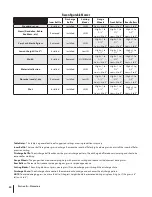
Reconfigurable Mower

Inner Baffle

Discharge

Baffle

Cutting 

Blades

Gauge 

Wheels

Front Roller

Rear Rollers

Standard set-up

Installed

Installed

Hi-lift

Low = 3 to 5”

Low = 3 to 5”

Low = 3 to 5”

Stems (Dandelion, Bahia, 

Buckhorn, etc.)

Removed

Installed

Hi-lift

High = 1 to 

2-1⁄2”

Low = 3 to 5”

High = 1 to 

2-1⁄2”

Low = 3 to 5”

High = 1 to 

2-1⁄2”

Low = 3 to 5”

Very Lush &/or tall grass

Removed

Installed

Hi-lift

High = 1 to 

2-1⁄2”

Low = 3 to 5”

High = 1 to 

2-1⁄2”

Low = 3 to 5”

High = 1 to 

2-1⁄2”

Low = 3 to 5”

Low cut height (1 to 2”)

Installed

Installed

Low-lift

High = 1 to 

2-1⁄2”

High = 1 to 

2-1⁄2”

High = 1 to 

2-1⁄2”

Mulch

Installed

Removed

Hi-lift/Mulch

High = 1 to 

2-1⁄2”

Low = 3 to 5”

High = 1 to 

2-1⁄2”

Low = 3 to 5”

High = 1 to 

2-1⁄2”

Low = 3 to 5”

Material collection

Installed

Installed

Hi-lift

High = 1 to 

2-1⁄2”

Low = 3 to 5”

High = 1 to 

2-1⁄2”

Low = 3 to 5”

High = 1 to 

2-1⁄2”

Low = 3 to 5”

Abrasive (sandy), dry

Removed

Installed

Low-lift

High = 1 to 

2-1⁄2”

Low = 3 to 5”

High = 1 to 

2-1⁄2”

Low = 3 to 5”

High = 1 to 

2-1⁄2”

Low = 3 to 5”

Wet

Installed

Installed

Hi-lift

High = 1 to 

2-1⁄2”

Low = 3 to 5”

High = 1 to 

2-1⁄2”

Low = 3 to 5”

High = 1 to 

2-1⁄2”

Low = 3 to 5”

Table Notes:

 This table is a general outline of suggested settings, mowing conditions may vary.

Inner Baffle: 

The inner baffle regulates grass discharge. Remove the inner baffle for high-volume grass and install the inner baffle for 

precision cutting.

Discharge Baffle:

 The discharge baffle enhances the grass discharge pattern. The discharge baffle reduces clumping and should be 

removed for mulching.

Gauge Wheels: 

The gauge wheels reduce scalping, help with precision cutting and reduce turf defacement during turns.

Rear Rollers:

 The rear rollers reduce scalping and gives grass a striped appearance.

Cutting Blades:

 The cutting blades cut grass, create grass lift and discharge grass through the discharge chute.

Discharge Chute: 

The discharge chute controls the mower deck discharge and enhances the discharge pattern

NOTE: 

To avoid damaging grass, no more than 1⁄3 of the grass height should be removed during a single cutting (i.e. if the grass is 6” 

tall, cut it to 4”).

Summary of Contents for Tank SZ

Page 1: ...n Practices Set Up Operation Maintenance Service Troubleshooting Warranty WARNING READ AND FOLLOW ALL SAFETY RULES AND INSTRUCTIONS IN THIS MANUAL BEFORE ATTEMPTING TO OPERATE THIS MACHINE FAILURE TO COMPLY WITH THESE INSTRUCTIONS MAY RESULT IN PERSONAL INJURY Form No 769 07369 February 23 2012 Tank SZ ...

Page 2: ...self with the machine its features and operation Please be aware that this Operator s Manual may cover a range of product specifications for various models Characteristics and features discussed and or illustrated in this manual may not be applicable to all models We reserve the right to change product specifications designs and equipment without notice and without incurring obligation If applicab...

Page 3: ...io 44136 0019 This spark ignition system complies with Canadian ICES 002 DANGER The engine manufacturer has supplied an engine owner s manual for information regarding US Environmental Protection Agency EPA and California Air resources Board CARB regulations relating to emission control systems maintenance and warranty Making any unauthorized alterations or modifications to the engine fuel or vent...

Page 4: ...aining this machine Long hair loose fitting clothing or jewelry may get entangled in moving parts Follow all federal state and local guidelines regarding the use of personal protective equipment 10 Be aware of the mower and attachment discharge direction and do not point it at anyone Do not operate the mower without the discharge cover or entire grass catcher in its proper place 11 Do not put hand...

Page 5: ...terrain could overturn the machine Tall grass can hide obstacles 3 Use slow speed Choose a low enough speed so that you will not have to stop while on the slope Avoid starting or stopping on a slope If the tires are unable to maintain traction disengage the blades and proceed slowly and carefully straight down the slope 4 Keep all movements on the slopes slow and gradual Do not make sudden changes...

Page 6: ... except when the ROPS are a Not properly installed and or not properly secured onto the machine b Damaged in such manner that their structural integrity has been compromised c Not in their fully upright and locked position 4 Seat belts are attached to the movable portion of the seat when suspension seats are utilized and therefore the seat mounting base must be secured to its pivot means and the p...

Page 7: ...el cap or add fuel while the engine is hot or running Allow engine to cool at least two minutes before refueling h Never over fill fuel tank Fill tank to no more than inch below bottom of filler neck to allow space for expansion i If necessary use a funnel to avoid spillage j Replace fuel cap and tighten securely k If fuel is spilled wipe off the engine and equipment Wait 5 minutes before starting...

Page 8: ...ay Tampering with the governor setting can lead to a runaway engine and cause it to operate at unsafe speeds Never tamper with factory setting of engine governor Notice Regarding Emissions This machine is equipped with an engine that is certified to federal EPA emission standards for non road engines and equipment and where applicable to California Air Resources Board CARB emission standards The e...

Page 9: ...p and throw objects which can cause serious personal injury BYSTANDERS Keep bystanders helpers children and pets at least 75 feet from the machine while it is in operation MAX 20 WARNING SLOPE OPERATION Do not operate this machine on a slope greater than 20 degrees DANGER ROTATING BLADES To reduce the risk of injury keep hands and feet away Do not operate unless discharge cover or grass catcher is...

Page 10: ...ee Figure 1 and Figure 2 4 Adjust gauge up or down until the left corner touches the slope See Figure 1 and Figure 2 5 If there is a gap below the gauge the slope is too steep for safe operation See Figure 2 above 2 0 d a s h e d l i n e Slope Gauge Figure 2 Figure 1 20 Slope 20 Slope WARNING Slopes are a major factor related to tip over and roll over accidents which can result in severe injury or...

Page 11: ...ion bypass valves 7 Remove the deck wash system nozzle adapter from the manual bag and store for future use Cut the wire tie holding the chute deflector up and discard any packing material NOTE All references in this manual to the left or right side and front or back of the machine are from the operating position only Exceptions if any will be specified TOOLSNEEDED Safety glasses leather gloves wi...

Page 12: ... the front if access is restricted NOTE The mounting hardware is accessible from the rear of the machine with the use of extensions Also access can be gained by reaching in from the sides over the tires fuel tanks 3 Install the reinforced plates flat washers and flange lock nuts but do not tighten See Fig 3 3 4 Install the upper ROPS section onto the lower ROPS posts Install the bolts retaining wa...

Page 13: ...lly pry off the steering wheel cover to remove the hardware 2 With the wheels of the machine pointing straight forward place the steering wheel over the steering shaft 3 Place the belleville washer over the steering wheel and secure with the hex lock screw See Fig 3 8 Steering Wheel Cover Hex Lock Screw Belleville Washer Figure 3 8 4 Place the steering wheel cover over the center of the steering w...

Page 14: ...the highest and lower the arm rest See Fig 3 10 Figure 3 10 Suspension Seat If equipped This machine is equipped with an adjustable seat which includes a retractable seat belt assembly and an Operator Presence Sensor OPS The OPS in the form of a switch is integrated into the seat bottom and is connected to the machine electrical system The seat can be adjusted forward and back the armrests can be ...

Page 15: ...rst followed by the NEGATIVE Black wire For shipping reasons both battery cables on your equipment may have been left disconnected from the terminals at the factory To connect the battery cables proceed as follows 1 Using the lever on the back of the seat frame lift up on the lever and tilt the seat forward NOTE The positive battery terminal is marked Pos The negative battery terminal is marked Ne...

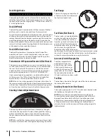
Page 16: ...he key from the ignition switch when the tractor is not in use Power Take Off PTO Switch The PTO switch is located on the LH console to the left of the operator s seat next to the ignition switch The PTO switch operates the electric PTO clutch mounted on the bottom of the engine crankshaft Pull the knob upward to engage the PTO clutch or push the knob downward to disengage the clutch The PTO switc...

Page 17: ... engine CHOKE ON PARK BRAKE OFF P Forward Drive Pedal The forward drive pedal is located on the right side of the machine along the running board Press the forward drive pedal forward to cause the tractor to travel forward Ground speed is also controlled with the forward drive pedal The further forward the pedal is pivoted the faster the tractor will travel The pedal will return to its original ne...

Page 18: ... tractor will eventually purge the air from the lines and the oil level will settle to the maximum Steering Column Adjustment Lever The steering column adjustment lever is located on the right side of the steering column To adjust the angle of the steering column rotate the lever down move the steering column to the desired position and then rotate the lever up to lock it into position NOTE Be sur...

Page 19: ...mbly Set Up section for instructions on adjusting the seat Safety Interlock System This machine is equipped with a safety interlock system for the protection of the operator If the interlock system should ever malfunction do not operate the machine Contact your authorized Cub Cadet Dealer The safety interlock system prevents the engine from cranking or starting unless the speed control pedals are ...

Page 20: ...ition switch NOTE Always remove the key from the ignition switch to prevent accidental starting or battery discharge if the equipment is left unattended Practice Operation Initial Use Operating a zero turn tractor is not like operating a conventional type riding tractor Although and because a zero turn tractor is more maneuverable getting used to operating the speed control pedals and the steering...

Page 21: ...o that the inside wheel is angled at approximately 88 degrees and the turn side tire will not rotate NOTE Making a pivot turn on grass will greatly increase the potential for defacement of the turf as well as potential damages to the traction surface and the tire Driving the Tractor In Reverse WARNING Always look behind and down on both sides of the tractor before backing up Always look behind whi...

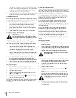
Page 22: ...when turning downhill Operating The PTO knob Operate the PTO knob as follows 1 Move the throttle control lever to approximately the mid throttle position 2 Pull the PTO knob switch upward to the ENGAGED position 3 Advance the throttle lever to the operating speed full engine speed 4 The operator must remain in the tractor seat at all times If the operator should leave the seat without turning off ...

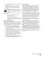
Page 23: ...at the engine should stop Mower Cutting Blades The blades normally factory installed on a mower afford the best grass cutting performance on the majority of grasses and mowing conditions however there will be occasions whereby the grass type stage of grass growth soil conditions and weather conditions will require different cutting blade types Since the mower decks are designed so that over lap of...

Page 24: ...2 1 2 Low 3 to 5 High 1 to 2 1 2 Low 3 to 5 Wet Installed Installed Hi lift High 1 to 2 1 2 Low 3 to 5 High 1 to 2 1 2 Low 3 to 5 High 1 to 2 1 2 Low 3 to 5 Table Notes This table is a general outline of suggested settings mowing conditions may vary Inner Baffle The inner baffle regulates grass discharge Remove the inner baffle for high volume grass and install the inner baffle for precision cutti...

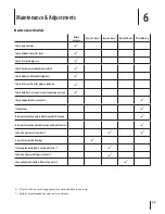
Page 25: ... fluid level in transmission oil expansion reservoir P Check engine intake screen cover P Clean mower P Blow out clean the pump control area under floor pan P Blow out clean the pedal control area under the foot rest P Lubricate wear points see chart P P Grease three spindle bearings P Clean engine cooling fins external surfaces P Lubricate all grease fittings see chart P Change hydrostatic fluid ...

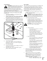
Page 26: ... Fluid Castrol Syntec Edge 5W50 recommended Spindle Lubricant Use only Shell Alvania RL 2 grease This grease is an amber colored grease designed for high speed bearing applications It has a base oil viscosity that reduces running losses has been formulated for low noise has excellent corrosion protection and has excellent bearing lubrication General Purpose Lubrication Use any NLGI grade 2 multi p...

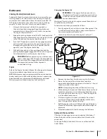
Page 27: ...eing done at owner s expense may be performed by any engine repair establishment or individual WarrantyrepairsmustbeperformedbyaCubCadetDealer Changing the Engine Oil WARNING If the engine has been recently run the engine muffler and surrounding metal surfaces will be hot and can cause burns to the skin Exercise caution to avoid burns Maintain oil level as instructed in engine manual Be careful no...

Page 28: ...ice the tire Balance inflation pressure between the rear tires to help maintain straight travel see tire side wall for proper pressure Keep the valve caps tightened to prevent air pressure loss Inflation Pressure Rear Tires 12 psi Front Tires 14 psi Leaking Tires When a flat tire occurs repair or replace immediately The normal procedure is to remove the wheel and replace it If a tire is getting so...

Page 29: ...torage 1 Change the engine oil and filter following the instructions provided in the engine manual WARNING Never store the tractor with fuel in the tank indoors or in poorly ventilated enclosures where fuel fumes may reach an open flame spark or pilot light as on a furnace water heater clothes dryer etc 2 If storing the tractor for 30 days or more a To prevent gum deposits from forming inside the ...

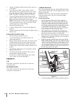
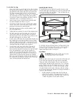
Page 30: ...to the Assembly Set Up section for instructions on adjusting the seat Steering Wheel Column Refer to the Assembly Set Up section for instructions on adjusting the steering wheel Leveling the Mower Deck When correctly adjusted the mower deck should be level side to side and the front of the deck should be approximately 1 4 lower than the rear of deck NOTE Check the tractor s tire pressure before pe...

Page 31: ... made by lowering or raising the height of cut link accordingly To raise the deck remove the shoulder bolt mounting the height of cut link to the lift handle and reassemble the shoulder bolt in the lowest of the three holes To lower the deck remove the shoulder bolts mounting the height of cut link flip the height of cut link around and reassemble the shoulder bolts in the top of the set of three ...

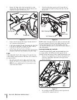
Page 32: ...TE There is a cable for each of the transmissions be sure to adjust both cables 2 Adjust the cable housing nuts one full turn and check parking capacity Repeat if parking brake does not hold See Fig 6 6 Left Transmission Right Transmission Cable Housing Nut Handbrake Bracket Figure 6 6 NOTE To adjust the right transmission cable it is recommended that you remove the left transmission cable by loos...

Page 33: ...ems If you have a recurring problem with blown fuses have the tractor s electrical system checked by your Cub Cadet Service Dealer Safety Switch Operation Checks The following operational checks should be made daily PTO Switch 1 Sit in the operator s seat With the drive pedals are in the neutral position and the parking brake engaged engage the PTO switch by pulling up on the knob and try to start...

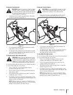
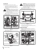
Page 34: ...e four lynch pins that secure the deck to the deck lift assembly See Fig 7 3 Lynch Pin Figure 7 3 CAUTION There is a certain amount of spring tension due to the weight of the deck When removing the lift linkage from the deck the tension of the springs will go from the deck to the deck lift pedal Not capturing the deck lift pedal while removing the lift linkage from the deck will cause it to snap b...

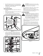
Page 35: ...acket 60 Deck 48 Deck Figure 7 7 WARNING Avoid pinching injuries Never place your fingers on the idler spring or between the belt and a pulley while removing the belt 5 Route the new belt as shown in Fig 7 7 Then reinstall the deck and PTO belt as instructed on pages 33 34 NOTE When replacing belts do not overtighten Adjust the idler pulley so that a ten pound pull with a spring scale between two ...

Page 36: ...all times 3 To properly sharpen the cutting blades remove equal amounts of metal from both ends of the blades along the cutting edges parallel to the trailing edge at a 25 30 angle Always grind each cutting blade edge equally to maintain proper blade balance See Fig 7 8 Figure 7 8 WARNING If a blade is bent or otherwise damaged replace the blade with a new one Use only original equipment blades WA...

Page 37: ...sembly See Fig 7 9 Spindle Assembly Blade Flange Lock Nut Spacer Hex Flange Bolt Support Plate Flange Lock Nut Hex Screw Spacer Figure 7 9 7 Reverse the process to install the spindle assembly Changing the Transmission Drive Belt Several components must be removed and special tools used in order to change the tractor s transmission drive belt See your Cub Cadet dealer to have the transmission driv...

Page 38: ...ressure 1 Perform side to side deck adjustment 2 Sharpen or replace blade 3 Check tire pressure in all four tires Mower will not mulch grass If Equipped w Mulching Kit 1 Engine speed too low 2 Wet grass 3 Excessively high grass 4 Dull blade 1 Place throttle in FAST rabbit position 2 Do not mulch when grass is wet 3 Mow once at a high cutting height then mow again at desired height or make a narrow...

Page 39: ... w Kawasaki KH 24 050 13 S Fuel Filter SZ 48 KH 25 050 22 S Fuel Filter SZ 60 w Kohler N A Fuel Filter SZ 60 w Kawasaki KH 12 050 01 S Oil Filter SZ 48 SZ 60 w Kohler N A Oil Filter SZ 60 w Kawasaki 754 04323 Deck Belt SZ 48 754 04319 Deck Belt SZ 60 754 04326 PTO Belt SZ 48 754 04296 PTO Belt SZ 60 754 04320 Drive Belt 02005017 Hi Lift Blade 17 0 SZ 48 02005019 Hi Lift Blade 21 0 SZ 60 02000920A ...

Page 40: ...59 Deck Wheel 925 1707D Battery 951 12193 Gas Cap 746 04534 Throttle Control 746 04812 Choke Control 725 05000 Ignition Key 01006693 Discharge Chute Assembly 02002666 Wheel Assembly SZ 48 23 x 9 50 12 634 04734 Wheel Assembly SZ 60 24 x 12 12 634 04704 Wheel Assembly 15 x 6 5 8 ...

Page 41: ...Attachments Accessories 10 41 Part No Part 59A30033150 Power Assist Triple Bagger 59A30036150 72 Snow Blade 59A30035150 Electric Deck Lift 490 850 0005 Blade Removal Tool 490 850 0008 Oil Siphon ...

Page 42: ...at cause the failure of a warranted part to be identical in all material respects to that part as described in MTD Consumer Group Inc s application for certification The warranty period begins on the date the outdoor equipment engine is delivered to an ultimate purchaser or first placed into service The warranty period is two years Subject to certain conditions and exclusions as stated below the w...

Page 43: ...till eligible for warranty coverage Further the coverage under this warranty extends only to parts that were present on the off road engine and equipment purchased The following emission warranty parts are covered if applicable 1 Fuel Metering System Cold start enrichment system soft choke Carburetor and internal parts or fuel injection system Fuel pump Fuel tank 2 Air Induction System Air cleaner...

Page 44: ...ual will void your warranty as to any resulting damage In addition Cub Cadet may deny warranty coverage if the hour meter or any part thereof is altered modified disconnected or otherwise tampered with HOW TO OBTAIN SERVICE Warranty service is available WITH PROOF OF PURCHASE AND APPLICABLE MAINTENANCE RECORDS through your local authorized service dealer To locate the dealer in your area In the U ...

Reviews: