background image

CUB CRAFTERS, INC. 

CC11-160 MAINTENANCE MANUAL 

Manual number SSC10000AMM  

5.4.15


Date: 01/31/2011 

Page: 5 


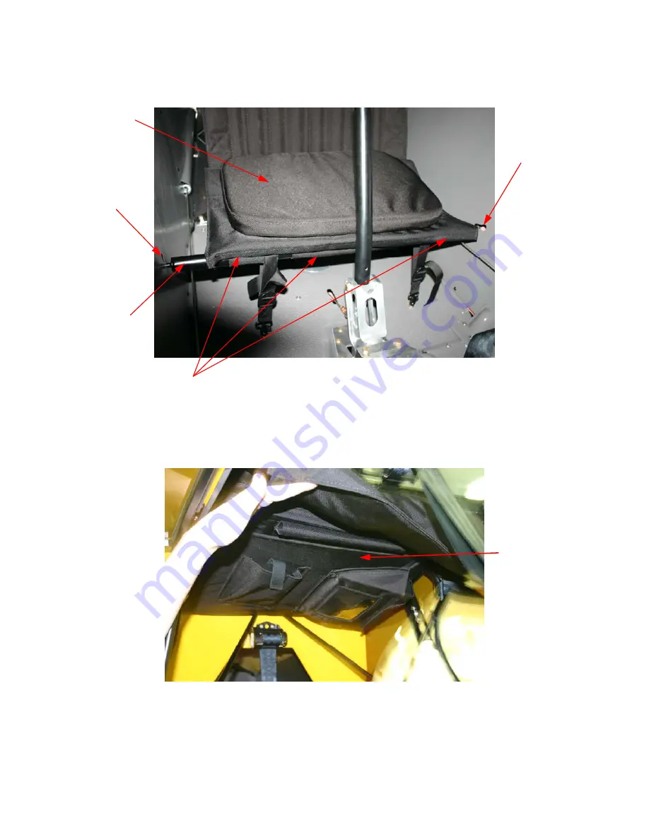
Figure 5 - Rear Cross Bar and Strap Attachment


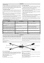
Fold rear seat up and stow in sling seat holder.  Place seat cushion and cross bar straps in sling 
seat holder.  See Figure 6. 


Figure 6 - Rear Seat Stowage in Sling Seat Holder 


Left Side Fuselage 
Cross Bar Slot 

Right Side Fuselage 

Cross Bar Slot 

Rear Seat Cushion 

Rear Seat Cross Bar Sleeves 

Sling Seat Holder

Cross Bar 

Summary of Contents for CARBON CUB SS CC11-160

Page 1: ...AIRCRAFT MAINTENANCE MANUAL S N CC11 00XXX Registration Number NXXXXX CUB CRAFTERS INC 1918 SOUTH 16TH AVENUE YAKIMA WASHINGTON 98903 USA 509 248 9491 877 484 7865 www cubcrafters com support cubcraf...

Page 2: ...INTENTIONALLY LEFT BLANK...

Page 3: ...1 6 3 4 6 3 5 6 3 8 6 3 10 6 3 11 6 3 12 6 3 13 6 3 14 6 3 15 6 3 16 6 3 17 6 3 18 6 3 19 6 3 23 6 3 24 and 6 A 10 28 2010 SJT SJH B List of Effective Pages Updated Added Section 5 4 15 Revised Sectio...

Page 4: ...CUB CRAFTERS INC CC11 160 MAINTENANCE MANUAL 0 Manual number SSC10000AMM Page ii Date 04 18 2013 INTENTIONALLY LEFT BLANK...

Page 5: ...Added Extended Range Tanks option Added Extended Range Schematic Updated all Avionic Information Added antenna locations Added Ignition Backup Battery Information Updated all schematics for Avionics I...

Page 6: ...Revised Engine Specifications and Data Oil Sump Capacity Revised Extended Range Fuel Tanks to 20 0 Gallons usable Revised Table 6 2 1 for Dual Tank Usable Fuel and Oil Capacity Corrected Typo in 11 3...

Page 7: ...ional drain Revision Date Updated Revised step c for electronic ignition Revision Date Updated Added Hartzell starter image Modified steps to replace lock washers Revision Date Updated Revised referen...

Page 8: ...CUB CRAFTERS INC CC11 160 MAINTENANCE MANUAL 0 Manual number SSC10000AMM Page vi Date 04 18 2013 THIS PAGE INTENTIONALLY LEFT BLANK...

Page 9: ...GEAR 5 4 7 WHEEL BRAKE ASSEMBLIES 5 4 8 ENGINE MOUNT 5 4 9 ENGINE 5 4 10 FUEL SYSTEM 5 4 11 PROPELLER 5 4 12 UTILITY SYSTEMS 5 4 13 AVIONICS AND INSTRUMENT SYSTEMS 5 4 14 ELECTRICAL SYSTEMS 5 4 15 SE...

Page 10: ...ON TO PERFORM OVERHAULS 8 2 OVERHAUL MANUAL for LSA or LSA COMPONENT 8 3 COMPONENTS PLANNED FOR OVERHAUL 8 3 1 ENGINE 8 3 2 PROPELLER 8 3 3 CARBURETOR 8 3 4 CARBURETOR AIR BOX 8 3 5 STARTERS GENERATOR...

Page 11: ...or address Alternatively complete the form on page 3 and email fax or mail to the address below E mail support cubcrafters com Fax 509 248 1421 Address 1918 South 16th Avenue Yakima WA 98903 Cub Craft...

Page 12: ...es the line maintenance minor repair and minor alteration tasks that can be accomplished by a holder of an LSA repairman certificate with either an inspection or maintenance rating No heavy maintenanc...

Page 13: ...ion Number CURRENT OWNER Last First NEW OWNER Last First COMPANY ORGANIZATION COMPANY ORGANIZATION PREVIOUS ADDRESS NEW ADDRESS Number and Street Number and Street City City State Province Postal Code...

Page 14: ...CUB CRAFTERS INC CC11 160 MAINTENANCE MANUAL 1 Manual number SSC10000AMM Page 4 Date 04 18 2013 INTENTIONALLY LEFT BLANK...

Page 15: ...MPANY ORGANIZATION ADDRESS Number and Street City AIRCRAFT MODEL CC11 _________________ State Province Postal Code AIRCRAFT SERIAL NUMBER CC11 _________________ Country AIRCRAFT REGISTRATION NUMBER TE...

Page 16: ...CUB CRAFTERS INC CC11 160 MAINTENANCE MANUAL 1 Manual number SSC10000AMM Page 6 Date 04 18 2013 INTENTIONALLY LEFT BLANK...

Page 17: ...ractice for Maintenance and the Development of Maintenance Manuals for Light Sport Aircraft ASTM F2245 Specification for the Design and Performance of a light Sport Aircraft ASTM F2295 Practice for Co...

Page 18: ...CUB CRAFTERS INC CC11 160 MAINTENANCE MANUAL 2 Manual number SSC10000AMM Page 2 Date 10 28 2010 INTENTIONALLY LEFT BLANK...

Page 19: ...teration a manufacturer has designated that requires specialized training equipment or facilities f Line Maintenance any repair maintenance scheduled checks servicing inspections or alterations not co...

Page 20: ...air or alterations that are only to be accomplished by the original manufacturer or a facility approved by the original manufacturer of the product o Overhaul Facility facility specifically authorized...

Page 21: ...1 4 SIGNIFICANCE AND USE The purpose of this maintenance manual is to provide guidance to owners mechanics airports regulatory officials and aircraft and component manufacturers who may accomplish mai...

Page 22: ...CUB CRAFTERS INC CC11 160 MAINTENANCE MANUAL 4 Manual number SSC10000AMM Page 2 Date 10 28 2010 INTENTIONALLY LEFT BLANK...

Page 23: ...CHAPTER 5 AIRCRAFT MAINTENANCE MANUAL...

Page 24: ...INTENTIONALLY LEFT BLANK...

Page 25: ...te 04 24 2009 Page i 5 AIRCRAFT MAINTANENCE MANUAL 5 1 FORMAT GUIDANCE FOR THE USE OF THIS MANUAL 5 2 GENERAL SPECIFICATIONS DATA 5 3 PERIODIC ANNUAL INSPECTION REQUIREMENTS 5 4 MAINTENANCE REPAIR ALT...

Page 26: ...CUB CRAFTERS INC CC11 160 MAINTENANCE MANUAL 5 Manual number SSC10000AMM Page ii Date 04 24 2009 INTENTIONALLY LEFT BLANK...

Page 27: ...MAINTENANCE MANUAL Manual number SSC10000AMM 5 1 Date 04 24 2009 Page 1 5 1 FORMAT GUIDANCE FOR THE USE OF THIS MANUAL TABLE OF CONTENTS 1 GENERAL 2 2 LAYOUT OF THE MANUAL 2 3 WARNINGS CAUTION AND NOT...

Page 28: ...ill have optional equipment for which there will be specific drawings that will either be included with the aircraft s documentation on delivery or be available from Cub Crafters Inc 2 LAYOUT OF THE M...

Page 29: ...raft owners and repair shops on a subscription basis Revisions will be sent to registered subscribers as they become available Revisions may also be obtained by submitting a request to Cub Crafters In...

Page 30: ...CUB CRAFTERS INC CC11 160 MAINTENANCE MANUAL 5 1 Manual number SSC10000AMM Page 4 Date 04 24 2009 INTENTIONALLY LEFT BLANK...

Page 31: ...S 5 2 EQUIPMENT LIST 6 3 PURCHASE PARTS SOURCE LISTS 7 3 1 Consumable or Frequently Replaced Items 7 4 ENGINE SPECIFICATIONS AND DATA 7 5 WEIGHT AND BALANCE DATA 8 6 TIRE INFLATION 8 7 APPROVED OILS A...

Page 32: ...WL Water Line is a vertical reference designation measured parallel to the ground from a point 38 53 inches below the center of the bolts that attach the landing gear to the fuselage BL Buttock Line i...

Page 33: ...CUB CRAFTERS INC CC11 160 MAINTENANCE MANUAL Manual number SSC10000AMM 5 2 Date 04 18 2013 Page 3 Figure 5 2 1 Aircraft Geometry Optional 3X3 Landing Gear F S is 59 50...

Page 34: ...opeller and 6 00x6 wheels 1 WINGS Type Externally Braced High Wing Airfoil Section USA 35B Mod at Root and Tip Chord at Root 63 in Dihedral measured on underside of front spar 0 75 Area 179 sq ft Aspe...

Page 35: ...Aileron Up 18 2 Aileron Down 18 2 Aileron Cable Tension 40 5 lbs b Flaps First Notch 15 3 Second Notch 35 3 Third Notch 50 3 c Stabilizers Neutral Setting 2 5 relative to longitudinal axis Stabilizer...

Page 36: ...a list of components and equipment that the operator is likely to change on the aircraft Description Ref In AMM 6 00x6 8 00x6 8 50x6 26 x6 29 x6 main wheel and tires 5 4 6 or 6 3 7 Main landing gear...

Page 37: ...CC340 Number of Cylinders 4 Bore Stroke 5 125 in x 4 125 in Compression Ratio 8 9 1 Piston Displacement 340 4 in3 Ignition Type Dual Electronic Rated Power at Sea Level 5 minutes 180 HP 2700 RPM Maxim...

Page 38: ...the fastener s manufacturer 8 2 Definitions Running Torque The average torque developed after the fastener is at least one full thread through the nut but prior to the tightening of the joint also cal...

Page 39: ...a fastener has been under torqued the nut shall be backed off one complete rotation 360 maximum and retightened to the specified value the bolt screw or stud must not be allowed to rotate 8 4 Use of T...

Page 40: ...both in feet etc for each calculation Different units must not be mixed 8 5 Torquing Patterns Figure 5 2 3 Torque Pattern Whenever applicable the following pattern must be followed when torquing fast...

Page 41: ...SION SHEAR TENSION SHEAR TENSION SHEAR AN363 AN365 NAS1021 MS21045 MS20365 MS20500 NAS679 AN364 MS20364 NAS1022 NAS1024 1030 NAS1067 1068 NAS680 687 NAS696 698 AN363 AN365 MS20365 MS21045 NAS1021 NAS1...

Page 42: ...ne who is essential to be in the area should be reminded that a spinning propeller may be lethal yet almost invisible Remove hats when running the engine to keep them from being removed by the propell...

Page 43: ...on so that flight safety information can be communicated in a timely manner Please report any service difficulties or any other issue relating to flight safety directly to Cub Crafters using the forms...

Page 44: ...CUB CRAFTERS INC CC11 160 MAINTENANCE MANUAL 5 2 Manual number SSC10000AMM Page 14 Date 04 18 2013 INTENTIONALLY LEFT BLANK...

Page 45: ...r SSC10000AMM 5 3 Date 10 28 2010 Page 1 5 3 PERIODIC AND CONDITION INSPECTION REQUIREMENTS TABLE OF CONTENTS 1 GENERAL 2 1 VISUAL INSPECTION 2 2 OPERATIONAL INSPECTION 3 3 FUNCTIONAL INSPECTION 3 2 C...

Page 46: ...have the latest editions of these publications This guide will not make reference to revision levels of vendor publications This guide will be applicable to the aircraft in the configuration it left...

Page 47: ...k intended to determine that a component or system is fulfilling its intended purpose The operational inspection does not require quantitative tolerances 3 FUNCTIONAL INSPECTION When called for by an...

Page 48: ...CUB CRAFTERS INC CC11 160 MAINTENANCE MANUAL 5 3 Manual number SSC10000AMM Page 4 Date 10 28 2010 3 6 5 10 11 9 7 8 1 4...

Page 49: ...ask of the inspection has been completed the Inspection Report is to be signed off in the log book maintenance record The inspection items to be covered in the condition inspection are identical to th...

Page 50: ...CUB CRAFTERS INC CC11 160 MAINTENANCE MANUAL 5 3 Manual number SSC10000AMM Page 6 Date 10 28 2010 INTENTIONALLY LEFT BLANK...

Page 51: ...RS AND ALTERATIONS OF PRIMARY STRUCTURES 5 4 1 GENERAL 5 4 2 FUSELAGE 5 4 3 WINGS 5 4 4 EMPENNAGE 5 4 5 FLIGHT CONTROLS 5 4 6 LANDING GEAR 5 4 7 WHEEL BRAKE ASSEMBLIES 5 4 8 ENGINE MOUNT 5 4 9 ENGINE...

Page 52: ...CUB CRAFTERS INC CC11 160 MAINTENANCE MANUAL 5 4 Manual number SSC10000AMM Page ii Date 04 24 2009 INTENTIONALLY LEFT BLANK...

Page 53: ...RAL No major repair or alterations as outlined in ASTM F2483 FAR 43 or in this manual are authorized at this time To obtain engineering approvals for any major repairs or alterations please contact Cu...

Page 54: ...CUB CRAFTERS INC CC11 160 MAINTENANCE MANUAL 5 4 1 Manual number SSC10000AMM Page 2 Date 04 24 2009 INTENTIONALLY LEFT BLANK...

Page 55: ...CUB CRAFTERS INC CC11 160 MAINTENANCE MANUAL Manual number SSC10000AMM 5 4 2 Date 04 24 2009 Page 1 5 4 2 FUSELAGE TABLE OF CONTENTS 1 GENERAL 2 2 MAINTENANCE 2...

Page 56: ...t gas fusion welding The steel structure is powder coated to protect it from corrosion Figure 5 4 2 1 Fuselage Frame 2 MAINTENANCE No major repair or alterations as outlined in ASTM F2483 FAR 43 or in...

Page 57: ...CUB CRAFTERS INC CC11 160 MAINTENANCE MANUAL Manual number SSC10000AMM 5 4 3 Date 04 24 2009 Page 1 5 4 3 WINGS TABLE OF CONTENTS 1 GENERAL 2 2 MAINTENANCE 2...

Page 58: ...ding light A stall warning vane is installed on the leading edge of the left wing The wing incorporates slotted wing flaps inboard of the ailerons 2 MAINTENANCE Refer to Section 6 3 4 for maintenance...

Page 59: ...CUB CRAFTERS INC CC11 160 MAINTENANCE MANUAL Manual number SSC10000AMM 5 4 4 Date 10 28 2010 Page 1 5 4 4 EMPENNAGE TABLE OF CONTENTS 1 GENERAL 2 2 MAINTENANCE 2...

Page 60: ...by an electric servo which moves the leading edge of the horizontal stabilizer up and down The servo is actuated with a rocker switch located on the front control stick Some aircraft are equipped with...

Page 61: ...CUB CRAFTERS INC CC11 160 MAINTENANCE MANUAL Manual number SSC10000AMM 5 4 5 Date 04 24 2009 Page 1 5 4 5 FLIGHT CONTROLS TABLE OF CONTENTS 1 GENERAL 2 2 MAINTENANCE 2...

Page 62: ...ll flaps 50 The flap lever has a spring latch system that holds the flap in the selected position To extend the flaps depress the trigger and then move the lever down To retract them depress the trigg...

Page 63: ...CUB CRAFTERS INC CC11 160 MAINTENANCE MANUAL Manual number SSC10000AMM 5 4 6 Date 04 24 2009 Page 1 5 4 6 LANDING GEAR TABLE OF CONTENTS 1 GENERAL 2 2 MAINTENANCE 2...

Page 64: ...hydraulically operated disc brakes actuated by pressing toe brakes at each crew position The tailwheel has leaf springs is steerable and has the ability to caster through 360 via the rudder pedals 2...

Page 65: ...CUB CRAFTERS INC CC11 160 MAINTENANCE MANUAL Manual number SSC10000AMM 5 4 7 Date 10 28 2010 Page 1 5 4 7 WHEEL AND BRAKE ASSEMBLIES TABLE OF CONTENTS 1 GENERAL 2 2 MAINTENANCE 2...

Page 66: ...dals and toggle the valve vertical is open horizontal is locked The master cylinders push hydraulic fluid to the calipers where two pistons are displaced and force the brake linings against a disc Eac...

Page 67: ...CUB CRAFTERS INC CC11 160 MAINTENANCE MANUAL Manual number SSC10000AMM 5 4 8 Date 10 28 2010 Page 1 5 4 8 ENGINE MOUNT TABLE OF CONTENTS 1 GENERAL 2 2 MAINTENANCE 2...

Page 68: ...ached to the mount through rubber mounts that help reduce vibration 2 MAINTENANCE No major repair or alterations as outlined in ASTM F2483 FAR 43 or in this manual are authorized at this time To obtai...

Page 69: ...CUB CRAFTERS INC CC11 160 MAINTENANCE MANUAL Manual number SSC10000AMM 5 4 9 Date 10 28 2010 Page 1 5 4 9 ENGINE TABLE OF CONTENTS 1 GENERAL 2 2 ENGINE MAINTENANCE 2...

Page 70: ...is adjusted manually with a control on the left side of the instrument panel Pulling the mixture control all the way back operates a cut off valve on the carburetor that stops the supply of fuel to t...

Page 71: ...CUB CRAFTERS INC CC11 160 MAINTENANCE MANUAL Manual number SSC10000AMM 5 4 10 Date 04 18 2013 Page 1 5 4 10 FUEL SYSTEMS TABLE OF CONTENTS 1 GENERAL 2 2 MAINTENANCE 3...

Page 72: ...located on the lower left side of the cockpit Both The engine is fed by both fuel tanks Left Fuel is supplied by the left tank Right Fuel is supplied by the right tank Off Fuel supply to the engine i...

Page 73: ...FTERS INC CC11 160 MAINTENANCE MANUAL Manual number SSC10000AMM 5 4 10 Date 04 18 2013 Page 3 FIGURE 5 4 10 1 STANDARD FUEL TANK CONFIGURATION FIGURE 5 4 10 2 OPTIONAL EXTENDED RANGE FUEL TANK CONFIGU...

Page 74: ...DITIONAL DRAIN S N 00264 AND ON Aircraft starting with S N 00264 have an additional sump and drain located on the bottom left side of the aircraft just aft of the firewall on the boot cowl The fuel sy...

Page 75: ...AIN 2 MAINTENANCE Refer to Section 6 3 15 for the maintenance of fuel system No major repair or alterations as outlined in ASTM F2483 FAR 43 or in this manual are authorized at this time To obtain eng...

Page 76: ...CUB CRAFTERS INC CC11 160 MAINTENANCE MANUAL 5 4 10 Manual number SSC10000AMM Page 6 Date 04 18 2013 THIS PAGE INTENTIONALLY LEFT BLANK...

Page 77: ...CUB CRAFTERS INC CC11 160 MAINTENANCE MANUAL Manual number SSC10000AMM 5 4 11 Date 04 24 2009 Page 1 5 4 11 PROPELLER TABLE OF CONTENTS 1 GENERAL 2 2 MAINTENANCE 2...

Page 78: ...al number SSC10000AMM Page 2 Date 04 24 2009 1 GENERAL The standard aircraft comes with a Catto Propellers Wood Fiberglass Composite Propeller 2 MAINTENANCE Refer to Section 6 3 16 or to the manufactu...

Page 79: ...CUB CRAFTERS INC CC11 160 MAINTENANCE MANUAL Manual number SSC10000AMM 5 4 12 Date 04 24 2009 Page 1 5 4 12 UTILITY SYSTEMS TABLE OF CONTENTS 1 GENERAL 2 2 MAINTENANCE 2...

Page 80: ...ovides air for the cabin heat system Hot air enters the cabin through an opening on floorboard To select the heater the control on the upper right part of the instrument panel must be pulled aft 2 MAI...

Page 81: ...E OF CONTENTS 1 GENERAL 2 2 INSTRUMENTS 5 3 COM SYSTEM 6 3 1 Garmin SL40 COM 6 3 2 Becker COM 7 3 3 PM1200 Intercom 7 3 4 PM3000 Intercom 7 4 NAVIGATION SYSTEM 8 4 1 Garmin GTX 327 Transponder 8 4 2 G...

Page 82: ...strument panel containing all flight navigation and engine instruments that are required for VFR operations Table 5 4 6 summarizes the equipment installed on the aircraft NOTE All instrument panel con...

Page 83: ...11 160 MAINTENANCE MANUAL Manual number SSC10000AMM 5 4 13 Date 04 18 2013 Page 3 Figure 5 4 6 3 Deluxe VFR II Instrument Panel Figure 5 4 6 4 Performance VFR Instrument Panel Figure 5 4 6 5 Deluxe Fl...

Page 84: ...l Tachometer Garmin SL40 COM Altimeter SmartMonitor S N 00237 and on Air Speed Indicator Oil Pressure Temperature Gauge Inclinometer skid slip indicator Deluxe VFR Instrument Panel Tachometer Garmin S...

Page 85: ...N 00237 and on PM1200 Intercom Optional Executive Glass Instrument Panel Airspeed Indicator Garmin SL40 COM Dynon D 180 EFIS and EMS Garmin GPS 695 696 GDU370 or GDU375 SmartMonitor S N 00237 and on G...

Page 86: ...lease contact Cub Crafters at Cub Crafters Inc 1918 South 16th Avenue Yakima WA 98903 Tel 509 248 9491 support cubcrafters com 3 1 Garmin SL40 COM Garmin SL40 incorporates pilot friendly features such...

Page 87: ...y the memory channel used or the supply voltage 3 3 PM1200 Intercom The PM1200 is a two place remote mount intercom designed to reduce noise that is picked up by the microphone dynamically reducing th...

Page 88: ...code button The GTX 327 also offers timing and display functions such as flight time and count up and count down timers as well as current pressure altitude 4 2 Garmin GTX 330 Transponder The GTX 330...

Page 89: ...ncoding altimeter is connected and Mode C is selected One button allows you to recall two preselected codes 4 4 Garmin GPS Options The Garmin GPSMAP 495 496 is an all in one versatile navigation syste...

Page 90: ...to have constant access to NEXRAF radar lightning METARs TAFs TFR and more In addition these units offer XM Satellite Radio capabilities featuring more than 150 digital channels of commercial free mu...

Page 91: ...venue Yakima WA 98903 Tel 509 248 9491 support cubcrafters com 5 1 Antenna Locations COM Antenna The COM antenna is attached to the belly panel directly underneath the pilot on the underside of the ai...

Page 92: ...CUB CRAFTERS INC CC11 160 MAINTENANCE MANUAL 5 4 13 Manual number SSC10000AMM Page 12 Date 04 18 2013 THIS PAGE INTENTIONALLY LEFT BLANK...

Page 93: ...SSC10000AMM 5 4 14 Date 10 28 2010 Page 1 5 4 14 ELECTRICAL SYSTEMS TABLE OF CONTENTS 1 GENERAL 2 2 ELECTRICAL POWER SYSTEMS 2 1 GENERAL 2 2 SCHEMATICS 3 3 LIGHTING SYSTEMS 9 1 GENERAL 9 2 SCHEMATICS...

Page 94: ...9 248 9491 support cubcrafters com 2 ELECTRICAL POWER SYSTEMS 1 GENERAL The aircraft uses a 14 volt DC electrical system with the power supplied by a 40 amp belt driven alternator and a 12 volt storag...

Page 95: ...CUB CRAFTERS INC CC11 160 MAINTENANCE MANUAL Manual number SSC10000AMM 5 4 14 Date 10 28 2010 Page 3 2 SCHEMATICS Figure 5 4 14 1 Electrical System Schematic without Ignition Backup Battery...

Page 96: ...CUB CRAFTERS INC CC11 160 MAINTENANCE MANUAL 5 4 14 Manual number SSC10000AMM Page 4 Date 10 28 2010 Figure 5 4 14 2 Electrical System Schematic with Ignition Backup Battery...

Page 97: ...CUB CRAFTERS INC CC11 160 MAINTENANCE MANUAL Manual number SSC10000AMM 5 4 14 Date 10 28 2010 Page 5 Figure 5 4 14 3 PM1200 Intercom System Schematic w Intercom...

Page 98: ...CUB CRAFTERS INC CC11 160 MAINTENANCE MANUAL 5 4 14 Manual number SSC10000AMM Page 6 Date 10 28 2010 Figure 5 4 14 4 Performance Avionics System Schematic w Intercom...

Page 99: ...CRAFTERS INC CC11 160 MAINTENANCE MANUAL Manual number SSC10000AMM 5 4 14 Date 10 28 2010 Page 7 Figure 5 4 14 5 PM3000 Intercom System Schematic Figure 5 4 14 6 Active Noise Reduction Intercom Syste...

Page 100: ...CUB CRAFTERS INC CC11 160 MAINTENANCE MANUAL 5 4 14 Manual number SSC10000AMM Page 8 Date 10 28 2010 Figure 5 4 14 7 Dynon Schematic...

Page 101: ...ay be installed on each wingtip These consist of navigation light and a strobe light There is also a position light on the tail of the aircraft An optional landing light may be mounted in the leading...

Page 102: ...CUB CRAFTERS INC CC11 160 MAINTENANCE MANUAL 5 4 14 Manual number SSC10000AMM Page 10 Date 10 28 2010 Figure 5 4 14 9 LED Lighting System Schematic S N 00107 and on...

Page 103: ...RAL The aircraft is supplied with an emergency locator transmitter ELT that meets TSO C91a The ELT is mounted in a bracket directly underneath the pilot s seat and may be accessed through an opening o...

Page 104: ...CUB CRAFTERS INC CC11 160 MAINTENANCE MANUAL 5 4 14 Manual number SSC10000AMM Page 12 Date 10 28 2010 INTENTIONALLY LEFT BLANK...

Page 105: ...CRAFTERS INC CC11 160 MAINTENANCE MANUAL Manual number SSC10000AMM 5 4 15 Date 01 31 2011 Page 1 5 4 15 SEATS TABLE OF CONTENTS 1 GENERAL 2 2 REAR SEAT STOWAGE 4 3 REAR SEAT INSTALLATION 6 4 MAINTENAN...

Page 106: ...is attached to the seat base at the front with screws on both sides There are two quick release T Handle pins one on each side at the rear of the seat to adjust the seat position See Figure 1 and 2 WA...

Page 107: ...ngers The seat is attached in front by a steel cross bar The steel cross bar is held in place to the floorboard by two cinched nylon straps The top of the rear seat is secured in place by straps integ...

Page 108: ...screw and push the screw in to allow the tab to rotate and slide pin out of seat base connector See Figure 4 Figure 4 Cross Bar Strap Attachment Remove cross bar from fuselage slots Slide the seat str...

Page 109: ...Strap Attachment Fold rear seat up and stow in sling seat holder Place seat cushion and cross bar straps in sling seat holder See Figure 6 Figure 6 Rear Seat Stowage in Sling Seat Holder Left Side Fus...

Page 110: ...ttom of the seat cushion and top of rear seat Ensure the straps in front of the seat are cinched tight enough to hold cross bar in slots at either end Ensure the top straps are secure and verify prope...

Page 111: ...CUB CRAFTERS INC CC11 160 MAINTENANCE MANUAL Manual number SSC10000AMM 5 5 Date 04 24 2009 Page 1 5 5 STRUCTURAL REPAIRS 1 GENERAL 2...

Page 112: ...r structural repairs or structural alterations as outlined in ASTM F2483 FAR 43 or in this manual are authorized at this time To obtain engineering approvals for any major repairs or alterations pleas...

Page 113: ...anual number SSC10000AMM 5 6 Date 10 28 2010 Page 1 5 6 PAINTING AND COATINGS Table of Contents 1 GENERAL 2 2 PAINTING 2 2 1 PREPARATION 2 1 PREPARATION OF METAL 2 2 PREPARATION OF COMPOSITES 2 3 PREP...

Page 114: ...will be used 2 PREPARATION OF COMPOSITES a Degrease components with an alcohol based cleaner per manufacturer s instructions b Sand with 400 grit sandpaper blow and tack off 3 PREPARATION OF FABRIC a...

Page 115: ...CHAPTER 6 LINE MAINTENANCE REPAIRS AND ALTERATIONS...

Page 116: ...INTENTIONALLY LEFT BLANK...

Page 117: ...10000AMM 6 Date 10 28 2010 Page i 6 LINE MAINTENANCE REPAIRS AND ALTERATIONS 6 1 AUTHORIZATION TO PERFORM LINE MAINTENANCE REPAIRS AND ALTERATIONS 6 2 LINE MAINTENANCE TASKS 6 3 REMOVAL REPLACEMENT OF...

Page 118: ...CUB CRAFTERS INC CC11 160 MAINTENANCE MANUAL 6 Manual number SSC10000AMM Page ii Date 10 28 2010 INTENTIONALLY LEFT BLANK...

Page 119: ...UAL Manual number SSC10000AMM 6 1 Date 10 28 2010 Page 1 6 1 GENERAL TABLE OF CONTENTS 1 AUTHORIZATION TO PERFORM LINE MAINTENANCE REPAIRS ALTERATIONS AND INSPECTIONS 2 2 FAA AUTHORIZATION FOR PILOT O...

Page 120: ...contained in FAA Advisory Circular 43 13 CUB CRAFTERS CARBON CUB SS MAINTENANCE BREAKDOWN DESCRIPTION OWNER OPERATOR OR ABOVE LSA REPAIRMAN I REPAIRMAN M A P OR REPAIR STATION REPAIRMAN M A P OR REPA...

Page 121: ...ip Lights X Landing Light X Vortex Generators X Tie Down Ring X Front Wing Strut X Rear Wing Strut X Ailerons X Flaps X Pitot Tube X Stall Warning X Fuel Tanks X Wing Assembly X ENGINE INSTALLATION En...

Page 122: ...Cub Crafters or Cub Crafters Delegate Brake Master Cylinder X Brake Lines and Fittings X Windshield X Sky Light X Front Windows X Rear Windows X Window Assembly X Door Assembly with Latch X Battery X...

Page 123: ...X COM Radio Removal X Intercom Removal X Transponder Removal X Bose Headset Wiring X Dynon Flight DEK D180 X Vertical Speed Indicator X Turn and Bank Indicator X Engine Primer X Clock X Primer X Landi...

Page 124: ...PERFORM LINE MAINTENANCE TASKS The tasks listed in this Manual and considered to be Minor Maintenance Repairs or Alteration tasks as defined in ASTM F2483 Section 3 1 12 and may be performed by the Pi...

Page 125: ...TERS INC CC11 160 MAINTENANCE MANUAL Manual number SSC10000AMM 6 2 Date 05 02 2011 Page 1 6 2 LINE MAINTENANCE TASKS TABLE OF CONTENTS 1 100 HOUR INSPECTION 2 2 CONDITION INSPECTION 2 3 SERVICING OF F...

Page 126: ...en the service and maintenance intervals when operating under abnormal environmental conditions such as high humidity and moisture salt water environments dusty atmospheric conditions extreme temperat...

Page 127: ...otal 40 US Gallons Usable Oil Phillips XC 20W50 6 Quarts Maximum 3 5 to 5 Quarts recommended for operation Hydraulic Fluid MIL H 5606G As required Main Tire Pressure 6 00 x 6 Dry Air 29 2 psi 8 00 x 6...

Page 128: ...n Pulley Shafts and Bushings LPS 2 MIL C 16173E GRADE 3 CLASS I Rudder Pedal Pivot Points Brake Pedal Pivot Points LPS 2 MIL C 16173E GRADE 3 CLASS I Flap Handle Shaft LPS 2 MIL C 16173E GRADE 3 CLASS...

Page 129: ...eel Bearings Mobilgrease 28 MIL G 81322E EMPENNAGE Stabilizer Tube Liners Mobilgrease 28 MIL G 81322E Elevator Hinge Pins LPS 2 MIL C 16173E GRADE 3 CLASS I Rudder Hinge Pins LPS 2 MIL C 16173E GRADE...

Page 130: ...CUB CRAFTERS INC CC11 160 MAINTENANCE MANUAL 6 2 Manual number SSC10000AMM Page 6 Date 05 02 2011 INTENTIONALLY LEFT BLANK...

Page 131: ...3 6 FLIGHT CONTROLS 6 3 7 LANDING GEAR 6 3 8 WHEEL AND BRAKE ASSEMBLIES 6 3 9 ENGINE MOUNT 6 3 10 ENGINE 6 3 11 ENGINE CONTROLS 6 3 12 AIR INDUCTION SYSTEMS 6 3 13 EXHAUST SYSTEM 6 3 14 ENGINE COWL 6...

Page 132: ...CUB CRAFTERS INC CC11 160 MAINTENANCE MANUAL 6 3 Manual number SSC10000AMM Page ii Date 04 18 2013 INTENTIONALLY LEFT BLANK...

Page 133: ...e airplane maintenance log Date of removal installation or overhaul of the component Time on the component since last overhaul if appropriate Aircraft s flight hours 1 Replacement Times ITEM INTERVAL...

Page 134: ...ture s Installation and Operation Manual 11 Remote ELT Switch Battery if installed 8 years Lithium 4 years Alkaline X 12 Fire Extinguisher 12 years from date of manufacture X Applicable to model RT A4...

Page 135: ...lace Under Tail Wing Jack Any Source Jack From Wing CAUTION Do not jack the aircraft outside or in an open hangar with winds in excess of 10 knots NOTE Raise airplane no more than required for the mai...

Page 136: ...Page 2 Date 08 31 2011 3 RAISING THE AIRCRAFT FROM THE LANDING GEAR Use this method to service the wheels and brakes a Place a chock under the opposite main wheel and tail wheel b Place a jack under t...

Page 137: ...HE WING Use this method for complete removal of landing gear leg a Place chock under opposite main wheel and tail wheel b Place jack between the main lift strut wing attachment point and the tie down...

Page 138: ...CUB CRAFTERS INC CC11 160 MAINTENANCE MANUAL 6 3 2 Manual number SSC10000AMM Page 4 Date 08 31 2011 INTENTIONALLY LEFT BLANK...

Page 139: ...CUB CRAFTERS INC CC11 160 MAINTENANCE MANUAL Manual number SSC10000AMM 6 3 3 Date 04 24 2009 Page 1 6 3 3 FUSELAGE TABLE OF CONTENTS 1 FUSELAGE 2 1 INSPECTION 2 2 REPAIR 2...

Page 140: ...6 A to perform periodic inspection tasks 2 REPAIR No major repair or alterations as outlined in ASTM F2483 FAR 43 or in this manual are authorized at this time To obtain engineering approvals for any...

Page 141: ...L Manual number SSC10000AMM 6 3 4 Date 09 03 2010 Page 1 6 3 4 WINGS TABLE OF CONTENTS 1 SERVICING 2 1 REMOVAL 4 2 INSTALLATION 5 2 RIGGING THE WINGS 7 1 PREPARATION 7 2 DIHEDRAL ANGLE 7 3 WASHOUT ANG...

Page 142: ...CUB CRAFTERS INC CC11 160 MAINTENANCE MANUAL 6 3 4 Manual number SSC10000AMM Page 2 Date 09 03 2010 1 SERVICING Figure 6 3 4 1 Wing Installation...

Page 143: ...CUB CRAFTERS INC CC11 160 MAINTENANCE MANUAL Manual number SSC10000AMM 6 3 4 Date 09 03 2010 Page 3 Figure 6 3 4 1 Wing Installation Continued...

Page 144: ...n plate covers from the wing Remove pulley and aileron upper cable attachment f Remove fairleads from wing strut Disconnect the lower aileron control cables from the torque tube link on the below the...

Page 145: ...ullets out with the bolts c Position the front strut fork on the fuselage attachment point and align the hole with a bullet d Align the top hole of the front strut with the wing attachment hole and se...

Page 146: ...e flap handle lever q Route the lower aileron cable down the strut r Install the associated pulley and fairleads Make sure the cable is not hooked on a strut s Connect the lower aileron control cables...

Page 147: ...ing tip above the front spar and pull tight and secure c Measure down from the string to the top of the inboard edge of the front spar cap Figure 6 3 4 2 The measurement should be 3 inches plus or min...

Page 148: ...washout of each wing by holding a straightedge on the end of a 30 inch level so that one end of the straightedge protrudes 0 38 3 8 inches above the level See Figure 6 3 4 2 Place this combination al...

Page 149: ...tor fell off it is dry and free of grease and dirt NOTE If the color of the vortex generator does not match the aircraft it is advisable to paint the exposed part of the vortex generator prior to inst...

Page 150: ...CUB CRAFTERS INC CC11 160 MAINTENANCE MANUAL 6 3 4 Manual number SSC10000AMM Page 10 Date 09 03 2010 INTENTIONALLY LEFT BLANK...

Page 151: ...URFACES 2 2 RUDDER 3 1 REMOVAL 3 2 INSTALLATION 4 1 ELEVATOR REMOVAL 5 2 HORIZONAL STABILIZERS REMOVAL 6 3 RIGHT HORIZONTAL STABILIZER INSTALLATION 7 4 LEFT HORIZONTAL STABILIZER INSTALLATION 9 5 INST...

Page 152: ...that are cracked e Check all control cables for wear or corrosion f Inspect all turnbuckles and turnbuckle terminals for cracks corrosion improper safety and freedom of movement g Damaged turnbuckles...

Page 153: ...OVAL Refer to Figure 6 3 5 1 a Unhook the tail wheel steering springs 1 from the rudder arm b Disconnect the rudder cables 2 from the rudder horn c Remove the rectangular inspection cover and disconne...

Page 154: ...rudder horn with a screw II Figure 6 3 5 3 washer III Figure 6 3 5 3 and nut IV Figure 6 3 5 3 Make certain the connections pivot freely and that the rudder is centered when rudder pedals are inline w...

Page 155: ...he hinge pins and pivot points with LPS 2 oil e Install the rectangular inspection cover 3 HORIZONTAL STABILIZERS AND ELEVATORS 1 ELEVATOR REMOVAL 1 Clevis Bolts 2 Washers 3 Castle Nuts 4 Cotter Pins...

Page 156: ...Carefully remove the clevis bolt 1 to disconnect the upper elevator cable connection 10 d Remove the cotter pin 4 nut 3 and washer 2 on the bottom side of the elevator horns 8 and 9 e Carefully remove...

Page 157: ...of the mounting points in the fuselage 3 RIGHT HORIZONTAL STABILIZER INSTALLATION 1 Long Bolt 4 Thick Washer 7 Rear Stabilizer Tube 2 Bolt 5 Nut 3 Thin Washer 6 Front Stabilizer Tube Figure 6 3 5 6 H...

Page 158: ...E Insert a short 3 16 inch bolt or cleco into each hole to hold the alignment and turn the stabilizer frame over It may be may be necessary to hold the alignment bolt in place with tape Drill a hole w...

Page 159: ...d If the tail surfaces have been changed and new tube liners are installed complete the following Have a second person pull the front corners of the stabilizer together tight against the fuselage att...

Page 160: ...G TAIL BRACE WIRES 1 Clevis Pin 2 Washer 3 Tail Fin 4 Rudder 5 Fin Stringer 6 Washer 7 Cotter Pin 11 Clevis Pin 12 Washer 13 Elevator 14 Horizontal Stringer 15 Horizontal Stabilizer 16 Washer 17 Cotte...

Page 161: ...of the aircraft on a sawhorse or bench b Level the stabilizer laterally at the rear spars by adjusting the bracing wires Refer to Section 6 3 22 c Place elevator trim in the center of the takeoff pos...

Page 162: ...vator horns 8 and 9 to the stabilizer and fuselage and secure with the bolt 5 washers 6 and lock nut 7 at the top of the horns d Attach the lower elevator cable connection 10 on the bottom of the elev...

Page 163: ...C10000AMM 6 3 5 Date 04 18 2013 Page 13 1 Clevis Bolts 2 Washers 3 Castle Nuts 4 Cotter Pins 5 Bolt 6 Washers 7 Lock Nut 8 Elevator Assembly Left Horn 9 Elevator Assembly Right Horn 10 Elevator Contro...

Page 164: ...n three threads shall be visible at each end of the turnbuckle barrels 2 RUDDER a Check that the rudder is centered when rudder pedals are inline with each other Ensure that the rudder can travel thro...

Page 165: ...NCE No major repair or alterations as outlined in ASTM F2483 FAR 43 or in this manual are authorized at this time To obtain engineering approvals for any major repairs or alterations please contact Cu...

Page 166: ...CUB CRAFTERS INC CC11 160 MAINTENANCE MANUAL 6 3 5 Manual number SSC10000AMM Page 16 Date 04 18 2013 INTENTIONALLY LEFT BLANK...

Page 167: ...CONTENTS 1 GENERAL 2 2 TROUBLESHOOTING 2 3 AILERONS 3 1 REMOVAL 3 2 INSTALLATION 4 3 RIGGING 6 4 FLAPS 8 1 REMOVAL 8 2 INSTALLATION 9 3 RIGGING THE POSITION OF THE FLAPS 10 5 FLAP HANDLE LOCK REPLACE...

Page 168: ...lace worn control stick stub or torque tube Excessive resistance to movement of control sticks Control cables too taut Adjust control cable tensions Pulleys binding Replace damaged pulleys Full elevat...

Page 169: ...ted properly Calibrate stall warning vane Stall warning does not work Problem in the electric circuit switches or horn Inspect and replace or repair damaged components 3 AILERONS 1 REMOVAL Refer to Fi...

Page 170: ...er SSC10000AMM Page 4 Date 04 24 2009 2 INSTALLATION 1 Bolt 2 Washers 3 Washer 4 Nut 5 Cotter Pin Refer to Figure 6 3 6 2 a Position the ailerons on the wing panels and secure with the bolts 1 washers...

Page 171: ...n Washer 9 Hinge Arm 10 Screw Figure 6 3 6 3 Installation of Control Cable on Aileron Horn Refer to Figure 6 3 6 3 b Attach each aileron control cable turnbuckle fork to the proper aileron horn with a...

Page 172: ...be rigged so that the top aft edge of the outboard end rib of either aileron does not extend more than 1 4 inch above or 1 4 inch below the top aft edge of the end wing rib with the control stick def...

Page 173: ...ends are locked in the hole Figure 6 3 6 6 Alternatively use the single wrap method with 032 stainless safety wire Figure 6 3 6 6 Safety of Turnbuckles NOTE Tight cables make stick action stiff while...

Page 174: ...MAINTENANCE MANUAL 6 3 6 Manual number SSC10000AMM Page 8 Date 04 24 2009 4 FLAPS 1 REMOVAL 1 Flap Hinge 2 Flap Cone Assembly 3 Cotter Pin 4 Castle Nut 5 Washer 6 Bolt 7 Steel Bushing 8 Bolt 9 Washers...

Page 175: ...r to Figure 6 3 6 7 and Figure 6 3 6 8 a Remove the cotter pin 3 and nut 4 holding the bolt 6 on the flap cone 2 and flap hinge 1 keep the bolt 6 in place temporarily b Remove the cotter pin A and nut...

Page 176: ...6 8 with a think or thick spacer washer E Figure 6 3 6 8 as necessary e Secure with a nut B Figure 6 3 6 8 and a cotter pin A Figure 6 3 6 8 snug nut to allow for proper flap and aileron function NOT...

Page 177: ...EPLACEMENT 1 REMOVE RETAINING HARDWARE 2 INSTALL NEW FLAP HANDLE LOCK 3 CHECK FLAP MOVEMENT a Ensure all flap positions are obtainable and there is no restriction to free movement in the flap handle s...

Page 178: ...NCE No major repair or alterations as outlined in ASTM F2483 FAR 43 or in this manual are authorized at this time To obtain engineering approvals for any major repairs or alterations please contact Cu...

Page 179: ...REMOVAL 8 2 INSPECTION 8 3 INSTALLATION 8 2 3 AOSS GEAR OPTIONAL 9 3 TAIL LANDING GEAR 10 3 1 STANDARD STEERABLE TAIL WHEEL 10 1 REMOVAL 10 2 DISASSEMBLY 11 3 CLEANING 11 4 INSPECTION 12 5 MINOR REPA...

Page 180: ...loose Ensure the tail wheel assembly is properly secured to the fuselage Tail Wheel assembled incorrectly Remove tail wheel assembly dismantle clean and reassemble Tail Wheel does not swivel Fork bind...

Page 181: ...master cylinder Leaky brake line connections Tighten or replace connectors Parking brake inoperative Parking brake valve defective Replace valve Unable to obtain sufficient hydraulic brake pressure ex...

Page 182: ...disc Replace with correct parts Brakes will not hold Lining worn below minimum wear limits Replace linings Discs worn below minimum wear limits Replace discs Contaminated lining Replace lining New lin...

Page 183: ...CUB CRAFTERS INC CC11 160 MAINTENANCE MANUAL Manual number SSC10000AMM 6 3 7 Date 04 29 2009 Page 5 2 MAIN LANDING GEAR Figure 6 3 7 1 Main Landing Gear Arrangement...

Page 184: ...by lifting the wing that is on the same side as the landing gear that is to be worked on The jack is placed at the forward wing strut to spar attachment point on the desired side see Section 5 3 2 d...

Page 185: ...nut to 160 200 in lbs b Place the bungee cover end over the top shaft of the shock assembly Align with the top shock hole and the holes in the cabane vee and insert bolt c Place the washer and the nu...

Page 186: ...mage and oversized holes b Replace or repair affected parts c Inspect the brake backing plates for cracks or excessive wear 3 INSTALLATION a Replace any hardware that is excessively corroded or worn b...

Page 187: ...th the nearest hole on the corresponding bolt j Safety the nuts with new cotter pins k Verify that all the hardware is installed properly and lower the aircraft to the ground l Reconnect the brake lin...

Page 188: ...ushing Figure 6 3 7 2 Standard Tail Wheel and Leaf Spring Installation a Lift the tail section of the airplane and rest the fuselage on a bench so the tail landing gear clears the ground b Disconnect...

Page 189: ...a Remove the tire assembly from the fork by removing the nut and sliding the axle out b Disengage the arm assembly washers and nut from the fork and bracket 3 CLEANING Clean all metal parts including...

Page 190: ...7 3 The components that make up the tail wheel assembly may not be repaired except that minor realignments are permitted such as minor dents and bends 6 REPLACEMENT OF PARTS Replace all nuts that have...

Page 191: ...all nuts v only finger tight c Insert the bushings x into the tail wheel assembly if they were removed d Insert the bolts ix through the bushings and tail wheel assembly e Hold in place with two washe...

Page 192: ...0AMM Page 14 Date 04 29 2009 3 2 OPTIONAL 3200 TYPE STEERABLE TAIL WHEEL 1 REMOVAL A Nut B Washer C Long Bolt D Clamp E Small Nut F Small Washer G Small Bolt H Large Area Nut I Bolt J Bushing K Adapte...

Page 193: ...e fuselage on a bench so the tail landing gear clears the ground b Disconnect the chain links from the tail wheel arms c Remove the front tail spring attach nut A and washer B d Disconnect the tail sp...

Page 194: ...Short Castle Nut 3 Washer 4 Fork Assy 5 Lower Dust Cap 6 Pawl 7 Thrust Washer 8 Arm Assy 9 Upper Dust Cap 10 Springs 11 Thrust Plate 12 Fiber Thrust Plate 13 Bracket Assy 14 Grease Retainer 15 Bearing...

Page 195: ...the bearings in a cleaning solution Dry all parts with compressed air 4 INSPECTION See Figure 6 3 7 4 and Figure 6 3 7 5 a Check the leaf springs for damage or twisting Figure 6 3 7 4 b Replace if co...

Page 196: ...ve and insert the bracket assembly 13 into the fork 4 maintaining the alignment of all the interlocking parts g Place the bearing 15 grease retainer 14 spacer 22 and washer 3 in the fork 4 Exert press...

Page 197: ...ge area nut H f Tighten the large area nut H to 270 300 in lbs g Tighten the nut A to 270 300 in lbs h Tighten the small nuts E to 70 100 in lbs i Reconnect the chain links to the tail wheel arms The...

Page 198: ...CUB CRAFTERS INC CC11 160 MAINTENANCE MANUAL 6 3 7 Manual number SSC10000AMM Page 20 Date 04 29 2009 INTENTIONALLY LEFT BLANK...

Page 199: ...MOVAL 2 2 WHEEL DISASSEMBLY 2 3 INSPECTION 4 4 WHEEL ASSEMBLY 5 5 MAIN WHEEL INSTALLATION 5 2 TAIL WHEEL 6 2 1 STANDARD WHEEL 6 2 2 3200 TYPE WHEEL 6 1 DISASSEMBLY 7 2 INSPECTION 7 6 REASSEMBLY 8 3 BR...

Page 200: ...ck under the axle and raise the tire off the ground See Section 6 2 4 2 e Remove the axle nut and wheel f The bearings can be removed cleaned and inspected without disassembling the wheel and removing...

Page 201: ...the wheel nuts 6 and washers 5 d Pull the wheel halves 1 3 apart being careful with the tubes valve stem e Remove the snap ring 11 grease seals 8 9 and bearing 2 Repeat on other wheel half 1 Inner Wh...

Page 202: ...ire should be removed when the tread is worn to the base of a groove Tires with wear through the top fabric layer can only remain in service long enough to return to a maintenance base to be replaced...

Page 203: ...olt 4 and torque to 85 95 in lbs g Refer to Section 6 2 for proper tire inflation h Allow time for the air trapped between the tube and tire to escape and recheck the pressure i Pack the bearings with...

Page 204: ...Inner Spacer 4 Bearing 5 Bearing Race 6 Bolt 7 Nut 8 Hub 9 Gasket 10 Tire 11 Tube CAUTION Care must be taken to avoid damaging wheel halves when breaking tire beads loose WARNING DO NOT ATTEMPT TO RE...

Page 205: ...ap and water Rinse with clean water and dry with a clean cloth b Visually inspect the tire inside and out for cuts uneven or excessive wear and penetration by foreign objects Replace if the tire is in...

Page 206: ...8 with the gasket 9 in between into the tire and tube assembly Make certain the gasket 9 is properly aligned with tube valve and hub bolt holes d Insert 4 bolts and engage with 4 nuts Torque to 80 100...

Page 207: ...160 MAINTENANCE MANUAL Manual number SSC10000AMM 6 3 8 Date 10 28 2010 Page 9 3 BRAKE CALIPERS 1 Safety Wire 2 Bolts 3 Brake Line 4 Caliper 5 Backing Plate 6 Anchor Lugs 7 Brake Back Plates Figure 6...

Page 208: ...calipers for leaks and excessive corrosion d If leaks are present at the pistons overhaul the caliper e Inspect the brake backing plate for cracks or excessive wear f Replace the parts if their condit...

Page 209: ...G BRAKE VALVE 1 Master Cylinder 2 90 Male Elbow 3 Ball Valve 4 90 Brass Poly Flow Fitting 5 Nylon 90 Tube Fitting 6 Brake Reservoir 7 Reservoir Plug 8 MS20392 2C17 Clevis Pin 9 MS20392 2C39 Clevis Pin...

Page 210: ...other damage 3 INSTALLATION See Figure 6 3 8 4 a Ensure center to center distance of bottom hole to upper hole on Master Cylinder 1 is 5 125 Adjust distance as required by twisting nut on Master Cyli...

Page 211: ...this time for the CC11 If any repairs or alteration tasks should be required to be performed before the release of this section of the manual it shall be accomplished using approved engineering data...

Page 212: ...CUB CRAFTERS INC CC11 160 MAINTENANCE MANUAL 6 3 8 Manual number SSC10000AMM Page 14 Date 10 28 2010 INTENTIONALLY LEFT BLANK...

Page 213: ...dix 6 A to perform periodic inspection tasks 2 REPAIR No major repair or alterations as outlined in ASTM F2483 FAR 43 or in this manual are authorized at this time To obtain engineering approvals for...

Page 214: ...CUB CRAFTERS INC CC11 160 MAINTENANCE MANUAL 6 3 9 Manual number SSC10000AMM Page 2 Date 04 24 2009 INTENTIONALLY LEFT BLANK...

Page 215: ...te 04 18 2013 Page 1 6 3 10 ENGINE TABLE OF CONTENTS 1 TROUBLESHOOTING SERVICING AND MAINTENANCE 2 2 SERVICING OIL SYSTEM 5 2 1 CHANGING ENGINE OIL 5 2 2 OIL SCREEN 6 1 REMOVAL 6 2 INSPECTION 6 3 INST...

Page 216: ...ve carburetor and repair 7 NOTE Carburetor screen or jets plugged Remove and clean 6 3 15 Insufficient priming weak explosions Repeat starting procedure with more priming Excess priming puffs of black...

Page 217: ...Idling jet plugged Clean carburetor 6 3 15 Water in fuel Drain sediment trap 6 3 15 Leak in air induction system Check all joints and throttle shaft bearings 6 3 12 Low power Defective ignition cable...

Page 218: ...sump Clean screen 7 NOTE Engine bearings worn Overhaul engine 8 NOTE Oil pressure gauge defective Test gauge and replace or repair 7 NOTE Internal oil leak Overhaul engine 8 NOTE Cracked crankcase co...

Page 219: ...oil screen and replace oil filter if installed f Close the oil drain making sure it is sealed g Fill the engine with an approved oil h Verify oil quantity with the dipstick i Secure dipstick j Install...

Page 220: ...o catch the oil c Remove the bolts 7 that secure the oil pressure screen housing d Drain the oil from the housing and remove the screen 2 2 INSPECTION a Inspect the screen 2 and inside the housing 3 f...

Page 221: ...nd case surfaces are clean 3 INSTALLATION c Assemble the screen 2 in the housing 3 assemble the gasket 1 and the housing 3 on mounting pad d Ensure that the gasket is properly oriented e Using new loc...

Page 222: ...ll but the most inner pipe thread on each elbow but not on the flare fitting threads Screw the elbows into the oil cooler Be very careful to start the threads properly and tighten with the elbow point...

Page 223: ...BLE ATTACHMENT 5 5 THROTTLE CABLE TO CARBURETOR ARM ATTACHMENT 7 6 INSPECTION 8 2 2 HEAVY DUTY THROTTLE CABLE 9 1 LEVER ATTACHMENT 9 2 LEVER INTERCONNECT LINKAGE 10 3 ATTACHMENT OF THROTTLE CABLE TO S...

Page 224: ...panel Pulling the mixture control all the way back operates a cut off valve on the carburetor that stops the supply of fuel to the engine 2 MAINTENANCE 2 1 PIN VICE GRIP THROTTLE CABLE 1 Throttle Lev...

Page 225: ...washers 4 a bushing 9 and nylon lock nuts 6 c The connecting rod 3 is secured to the throttle levers with a AN525 screw 5 washers 4 castle nut and cotter pin 7 d The throttle cable end is secured to t...

Page 226: ...TTACHMENT OF THROTTLE CABLE TO SIDE PANEL Figure 6 3 11 3 Attachment of Throttle to Side Panel Refer to Figure 6 3 11 3 The throttle plates 4 are kept from moving by six AN525 screws 3 that are bolted...

Page 227: ...TOR MOUNT THROTTLE CABLE ATTACHMENT Refer to Figure 6 3 11 4 The throttle cable 1 is held in place to the mixture bracket 4 and secured with a cable clamp 3 bolt washer and nut 1 Throttle Cable 2 Mixt...

Page 228: ...Page 6 Date 10 28 2010 1 Throttle Cable 2 Mixture Cable 3 Clamp 4 Clamp 5 Bolt 6 Washer 7 Nut Figure 6 3 11 5 Attachment of Throttle Cable to Firewall Refer to Figure 6 3 11 5 The throttle cable is h...

Page 229: ...Arm Refer to Figure 6 3 11 6 e The throttle cable is secured to the carburetor arm with a bolt 1 through bushings 4 a washer 6 a nut 2 and a cotter pin 5 f The throttle travel can be adjusted by scre...

Page 230: ...in the cabin have positive clearance from the panel h Move the throttle to either full open or full closed inspect cable attachment at the carburetor Repeat the same procedure with the full opposite...

Page 231: ...1 Throttle Lever 2 Throttle Lever Plate 3 Throttle Linkage Rod 4 Washers 5 AN525 Screws 6 Nylon Lock Nut 7 Cotter Pin 8 Phenolic Spacer 9 Bushing 10 Throttle Cable 11 Cable Nut 13 MS35812 1 Clevis 14...

Page 232: ...ing 9 and nylon lock nuts 6 c The connecting rod 3 is secured to the throttle levers with a AN525 screw 5 washers 4 castle nut and cotter pin 7 d The heavy duty throttle cable is secured to the clevis...

Page 233: ...SSC10000AMM 6 3 11 Date 10 28 2010 Page 11 3 ATTACHMENT OF THROTTLE CABLE TO SIDE PANEL Figure 6 3 11 9 Attachment of Throttle to Side Panel Dual and Single Throttle Attachments Shown 1 Throttle Lever...

Page 234: ...the left hand composite side panel 2 4 MOTOR MOUNT THROTTLE CABLE ATTACHMENT Figure 6 3 11 10 Attachment of Throttle to Engine Mount Tube Bracket Refer to Figure 6 3 11 10 The throttle cable 1 is hel...

Page 235: ...2 Throttle Cable Figure 6 3 11 11 Routing of Throttle Cable through Firewall Refer to Figure 6 3 11 11 The heavy duty throttle cable is directly routed through a hole in the firewall to the engine mou...

Page 236: ...e bearing rod end Be sure that the bearing rod end jam nut is retightened after making any adjustment 6 INSPECTION a Ensure that the throttle arm at the carburetor contacts both stops at either extrem...

Page 237: ...e Nut Figure 6 3 11 13 Mounting of the Mixture Control at the Instrument Panel Refer to Figure 6 3 11 13 a The mixture control knob 1 is secured to the instrument panel 4 with a lock washer 5 and a nu...

Page 238: ...a bolt washers and a nut b The mixture bracket is secured to the engine mount with a bolt a washer and a nut The position of the cable housing in the mixture bracket clamp affects the travel of the kn...

Page 239: ...el Arm Refer to Figure 6 3 11 15 a The control cable rod pivots the mixture control lever on the carburetor The rod is held tight by the mixture swivel fitting b Adjusting the cable rod length at the...

Page 240: ...retor contacts both stops at either extreme of its travel At the same time there should be no more than cushion between the knob and the panel nut in the full rich position b Inspect to be sure the ca...

Page 241: ...anual number SSC10000AMM 6 3 12 Date 10 28 2010 Page 1 6 3 12 INDUCTION SYSTEM TABLE OF CONTENTS 1 GENERAL 2 1 1 AIR FILTER 2 1 REMOVAL 3 1 INSPECTION 3 2 INSTALLATION 3 1 2 CARBURETOR HEAT 4 1 INSTAL...

Page 242: ...utterfly valve that allows heated unfiltered air to feed into the carburetor The carburetor heat control is located on the instrument panel CAUTION Ground operations with the carburetor heat control i...

Page 243: ...ter for any damage such as tears or large holes b Clean the filter in a mild degreasing cleanser to remove dirt and other particles Wring the excess from the element and allow it to dry c Apply a filt...

Page 244: ...swivel fitting stud b Insert the threaded end of the stud through the swivel fitting and through the carburetor heat valve arm c Place the AN960 10 washer and AN310 3 castle nut on the stud and tight...

Page 245: ...ERS INC CC11 160 MAINTENANCE MANUAL Manual number SSC10000AMM 6 3 13 Date 10 28 2010 Page 1 6 3 13 EXHAUST SYSTEM TABLE OF CONTENTS 1 GENERAL 2 1 1 ENGINE EXHAUST 3 1 REMOVAL 3 2 INSPECTION 3 3 INSTAL...

Page 246: ...UAL 6 3 13 Manual number SSC10000AMM Page 2 Date 10 28 2010 1 GENERAL The exhaust system is a four into one system Shrouds mounted on the exhaust lines provide provision for both carburetor heat and c...

Page 247: ...nd lower the exhaust system away from the engine 2 INSPECTION a Inspect the components of the exhaust system for signs of cracking Have any cracks repaired by an FAA approved or Cub Crafters approved...

Page 248: ...CUB CRAFTERS INC CC11 160 MAINTENANCE MANUAL 6 3 13 Manual number SSC10000AMM Page 4 Date 10 28 2010 INTENTIONALLY LEFT BLANK...

Page 249: ...TENANCE MANUAL Manual number SSC10000AMM 6 3 14 Date 10 28 2010 Page 1 6 3 14 ENGINE COWL TABLE OF CONTENTS 1 GENERAL 2 1 1 ENGINE COWL 2 1 COWL REMOVAL 2 2 INSPECTION 3 3 INSTALLATION 3 1 2 COWL FLAP...

Page 250: ...1 ENGINE COWL Figure 6 3 14 1 Lower Access Panel 1 COWL REMOVAL a Remove screws along lower access panel 10 qty Be sure hold on to the air filter so it does not fall to the ground b Disconnect the ind...

Page 251: ...n place secure the cowl to the fuselage with screws b Carefully position the upper cowl in place secure it to the lower cowl and to the fuselage with screws c Make sure the baffle seal is properly for...

Page 252: ...is recommended the flaps be in the closed position during the winter months They can be adjusted accordingly as conditions dictate a Remove lower cowl as directed in 1 1 Cowl Removal b Remove screw A...

Page 253: ...6 3 15 Date 04 18 2013 Page 1 6 3 15 FUEL SYSTEMS TABLE OF CONTENTS 1 SERVICING 2 1 DRAINING FUEL 2 2 FUEL TANKS 3 1 TROUBLESHOOTING 4 2 MAINTENANCE 5 3 FUEL FILTERS 6 1 FUEL STRAINER SERVICING 6 2 C...

Page 254: ...ng the de fueling operation Operation of any electrical switch during the fueling operation is prohibited Do not allow smoking or open flames within 100 feet of the aircraft or fuel servicing vehicle...

Page 255: ...FTERS INC CC11 160 MAINTENANCE MANUAL Manual number SSC10000AMM 6 3 15 Date 04 18 2013 Page 3 2 FUEL TANKS Figure 6 3 15 1 Standard Fuel System Schematic Figure 6 3 15 2 Extended Range Fuel System Sch...

Page 256: ...160 MAINTENANCE MANUAL 6 3 15 Manual number SSC10000AMM Page 4 Date 04 18 2013 Figure 6 3 15 3 Standard Fuel System Schematic with Additional Drain Figure 6 3 15 4 Extended Range Fuel System Schematic...

Page 257: ...Seal Replace Fuel Cap Seal Leak in Fuel Line Loose Connector s Inspect and Tighten Connector s Chaffing Replace Fuel Line Defective Thread Replace Threaded Component 3 MAINTENANCE No major repair or a...

Page 258: ...1 160 MAINTENANCE MANUAL 6 3 15 Manual number SSC10000AMM Page 6 Date 04 18 2013 3 FUEL FILTERS 1 FUEL STRAINER SERVICING 1 Cotter Pin 2 O Ring 3 Screen 4 Clip 5 Top Support 6 Bowl Figure 6 3 15 5 Fue...

Page 259: ...er under the bowl to catch the residual fuel e Twist bowl 6 to remove and empty the residual fuel f Remove the wire snap ring 4 with fingers and gently remove the screen 3 g Inspect and clean the scre...

Page 260: ...04 18 2013 2 CARBURETOR INLET SCREEN SERVICING a Turn fuel selector to OFF position b Remove the large hex plug in the left side of the float chamber c Clean the screen and flush accumulations of dirt...

Page 261: ...Drain the fuel tanks through the drains located on the underside of the fuselage and fuel strainer b Drain the remaining fuel out the fuel strainer drain c Remove the selector handle and handle butto...

Page 262: ...et of balls and springs 4 h Remove the small O ring 5 and the large O rings 6 then clean the barrel i Inspect for wear and grooves j Replace the small O ring 5 and the large O rings 6 with new and lub...

Page 263: ...ANCE No major repair or alterations as outlined in ASTM F2483 FAR 43 or in this manual are authorized at this time To obtain engineering approvals for any major repairs or alterations please contact C...

Page 264: ...CUB CRAFTERS INC CC11 160 MAINTENANCE MANUAL 6 3 15 Manual number SSC10000AMM Page 12 Date 04 18 2013 THIS PAGE INTENTIONALLY LEFT BLANK...

Page 265: ...C11 160 MAINTENANCE MANUAL Manual number SSC10000AMM 6 3 16 Date 04 18 2013 Page 1 6 3 16 PROPELLERS TABLE OF CONTENTS 1 CATTO PROPELLER 2 1 TROUBLESHOOTING 2 2 REMOVAL 2 3 INSPECTION 2 4 INSTALLATION...

Page 266: ...is still present dynamic propeller balancing may be required 2 REMOVAL a Remove the spinner b Cut and remove the safety wire from the propeller bolts c Remove the propeller bolts Assistance may be ne...

Page 267: ...ry c Turn ignition switch to OFF and ensure that all circuit breakers are pulled d Place the spinner backing plate on the crankshaft flange ensuring the prop blade orientation is correct e Position th...

Page 268: ...NCE No major repair or alterations as outlined in ASTM F2483 FAR 43 or in this manual are authorized at this time To obtain engineering approvals for any major repairs or alterations please contact Cu...

Page 269: ...1 GENERAL 2 2 TROUBLESHOOTING 3 3 STARTER 4 1 GENERAL 4 2 TROUBLESHOOTING 5 3 REMOVAL 5 4 INSPECTION 5 5 INSTALLATION 5 2 ALTERNATOR 6 1 GENERAL 6 2 REMOVAL 6 3 INSPECTION 6 4 INSTALLATION 6 4 MAIN B...

Page 270: ...L No major repair or alterations as outlined in ASTM F2483 FAR 43 or in this manual are authorized at this time To obtain engineering approvals for any major repairs or alterations please contact Cub...

Page 271: ...tal volt ohmmeter DVM to make the following checks WARNING THE ENGINE SHOULD NOT BE RUNNING AND THE IGNITION SWITCHES SHOULD BE OFF a Turn all switches off Use the lowest resistance scale on the DVM C...

Page 272: ...AL 6 3 17 Manual number SSC10000AMM Page 4 Date 04 18 2013 3 STARTER 1 GENERAL The starter is a 12 Volt High Torque starter with a built in electro mechanical pinion to actuate the gear Figure 6 3 17...

Page 273: ...g to starter Starter solenoid defective Replace starter solenoid Starter drive gear stays engaged for some length of time after the ignition switch is released Stuck starter solenoid Replace faulty st...

Page 274: ...s b Remove the mounting bolts 3 INSPECTION c Inspect the alternator for general condition Broken wires or damaged connectors may be corrected in the field All other repairs must be carried out by qual...

Page 275: ...s 3 CHARGING NOTE Charging should be conducted in an environment between 70 F and 90 F 20 C and 30 C The battery capacity may vary if charged outside of this recommended temperature range NOTE If batt...

Page 276: ...d remove battery cover bracket c Remove battery d Disconnect terminals 2 INSPECTION a Inspect the battery and terminals for condition and corrosion b Clean as required c If necessary charge the batter...

Page 277: ...attery a The battery may be charged using a 12 volt 1 ampere battery charger 4 INSTALLATION a Connect negative lead the black heat shrink covered wire to battery b Connect positive lead the wire with...

Page 278: ...CUB CRAFTERS INC CC11 160 MAINTENANCE MANUAL 6 3 17 Manual number SSC10000AMM Page 10 Date 04 18 2013 INTENTIONALLY LEFT BLANK...

Page 279: ...MANUAL Manual number SSC10000AMM 6 3 18 Date 10 28 2010 Page 1 6 3 18 POWERPLANT IGNITION TABLE OF CONTENTS 1 SPARK PLUGS 2 1 REMOVAL 2 2 INSPECTION 2 3 INSTALLATION 2 2 ELECTRONIC IGNITION 3 1 REMOV...

Page 280: ...rial lodged between electrodes or around the insulator that could be conductive Clean as needed b Check the electrode gap It should be between 032 040 Re set if necessary c Check connector for any abn...

Page 281: ...s 1 3 2 4 The dual system is connected such that each system knows if the other one is operating If one of the two systems is turned off or has failed the remaining system will automatically shift its...

Page 282: ...C340 Engine Maintenance Manual and manuals from Light Speed Engineering for the Plasma III ignition system 2 INSTALLATION a Refer to the CC340 Engine Maintenance Manual and manuals from Light Speed En...

Page 283: ...L Manual number SSC10000AMM 6 3 19 Date 10 28 2010 Page 1 6 3 19 ELECTRICAL TABLE OF CONTENTS 1 GENERAL 2 2 LANDING AND TAXI LIGHTS 3 3 INCANDESCENT LIGHTING SYSTEM 3 4 LIGHTWEIGHT LED NAVIGATION LIGH...

Page 284: ...e landing taxi light on the leading edge of the left wing The flight instruments are unlit but glass panel and or GPS units are integrally lighted There is a map light located on the upper right panel...

Page 285: ...TION a Attach wiring b Reposition front mounting plate and secure with 4 screws c Reattach the lens being very careful not to crack the Plexiglas 3 INCANDESCENT LIGHTING SYSTEM 1 TROUBLESHOOTING PROBL...

Page 286: ...t section 3 INSTALLATION b Refer to Navigational light section 4 LIGHTWEIGHT LED NAVIGATION LIGHTS AND ANTI COLLISION 1 GENERAL The LED navigation and anti collision lights are integrated into single...

Page 287: ...CUB CRAFTERS INC CC11 160 MAINTENANCE MANUAL Manual number SSC10000AMM 6 3 20 Date 04 24 2009 Page 1 6 3 20 STALL WARNING SYSTEM TABLE OF CONTENTS 1 GENERAL 2 2 STALL WARNING SWITCH ADJUSTMENT 2...

Page 288: ...e circuit and activating the horn 2 STALL WARNING SWITCH ADJUSTMENT The stall horn should be activated at a speed that is no less than 6 MPH prior to the stall occurring in any configuration On the ot...

Page 289: ...NTENANCE MANUAL Manual number SSC10000AMM 6 3 21 Date 04 24 2009 Page 1 6 3 21 HOSES AND LINES For replacement hoses please contact Cub Crafters Inc 1918 South 16th Avenue Yakima WA 98903 Tel 509 248...

Page 290: ...CUB CRAFTERS INC CC11 160 MAINTENANCE MANUAL 6 3 21 Manual number SSC10000AMM Page 2 Date 04 24 2009 INTENTIONALLY LEFT BLANK...

Page 291: ...riate 2 PREPARATION a Place the aircraft in a hangar with the doors closed where the wind will not affect the aircraft b Place the aircraft approximately in a flight level attitude by supporting the t...

Page 292: ...000AMM Page 2 Date 04 24 2009 4 LATERAL LEVELING Place the level on the upper forward cross tube located in the cabin just behind the windshield as shown in Figure 6 3 22 2 Center the bubble to level...

Page 293: ...Prior to leaving the factory the aircraft was weighed and the C G location was computed You will find this information in paragraph 6 4 of the Pilot s Operating Handbook and Aircraft Flight Manual If...

Page 294: ...Actual Weight Arm Moment 1 Left Main Wheel 59 50 in 2 Right Main Wheel 59 50 in 3 Tail Wheel 261 90 in TOTAL WEIGHT Weight in Lines 1 2 3 TOTAL MOMENT Moment in Lines 1 2 3 Table 6 3 23 2 3X3 Landing...

Page 295: ...ber SSC10000AMM 6 3 24 Date 10 28 2010 Page 1 6 3 24 PARKING AND MOORING TABLE OF CONTENTS 1 PARKING 2 2 MOORING 2 3 STORAGE 4 3 1 GENERAL 4 3 2 MAINTENANCE PRACTICES 4 1 TEMPORARY STORAGE 30 to 90 Da...

Page 296: ...arings and getting flat spots on the tires 2 MOORING a Position the airplane on level surface and headed into the wind b Set the parking brakes The parking brake valves are located on the forward port...

Page 297: ...CUB CRAFTERS INC CC11 160 MAINTENANCE MANUAL Manual number SSC10000AMM 6 3 24 Date 10 28 2010 Page 3 Figure 6 3 24 1 Wing Tie Down Figure 6 3 24 2 Tailwheel Tie Down...

Page 298: ...cture s Service Letter c Fill the fuel tanks completely Check for water accumulating each week d Wipe the tires with dry cloth and treat them with tire protector spray Mark the tire positions and date...

Page 299: ...cessary Refer to Chapter 6 2 3 NOTE It is advisable to use unserviceable tires for prolonged storage e Remove the battery Refer to Chapter 6 3 14 and the ELT batteries Refer to Chapter 5 4 14 and stor...

Page 300: ...service letter b Remove all covers tapes and tags from airplane c Reinstall the engine battery Refer to Chapter 6 3 14 and the ELT batteries Refer to Chapter 5 4 14 d Fill the fuel tanks if applicable...

Page 301: ...s 2 1 APPROVED FABRIC REPAIR MATERIALS 2 2 INSPECTION OF FABRIC 2 3 FABRIC REPAIRS 2 4 SIZE OF REPAIR AREA 3 5 PATCH REPAIR LESS THAN 8 INCHES 4 6 PATCH REPAIR MORE THAN 8 INCHES 6 7 STITCHING 6 3 NON...

Page 302: ...od shape Ultraviolet radiation in other words direct sunlight is the main cause of deterioration of the fabric The fabric is treated at the factory to protect it from this type of radiation The fabric...

Page 303: ...m of the patch If the length of the damaged area is less than 8 inches in length the patch must overlap the old fabric by at least 1 inch Finishing tapes are not required over the glued seams unless t...

Page 304: ...ts as a shrinking panel to re tighten the fabric in the area of the repair Use a piece of cardboard as a shield to keep the iron off the glued areas if needed h Poly Brush requires two applications Ea...

Page 305: ...Smooth tape and doubler edges using dry 320 grit sandpaper to remove surface dust bumps Blow and tack off the covering to be sure it is as dust free as possible Spray or brush the third coat of Poly...

Page 306: ...t 7 STITCHING A modified seine knot will be used for stitching and the knots and stitches will be hidden under the fabric The following text and sketches describe how this is accomplished Tie the firs...

Page 307: ...6 4 1 The lace may be rotated to place the knot under the fabric before cutting the cord 8 FABRIC RIVETS Approved blind rivets can be used to secure the fabric to the center and trailing edge ribs in...

Page 308: ...CUB CRAFTERS INC CC11 160 MAINTENANCE MANUAL 6 4 Manual number SSC10000AMM Page 8 Date 04 18 2013 Figure 6 4 2 Rib Stitching Steps 1 to 4...

Page 309: ...CUB CRAFTERS INC CC11 160 MAINTENANCE MANUAL Manual number SSC10000AMM 6 4 Date 04 18 2013 Page 9 Figure 6 4 3 Rib Stitching Steps 5 to 8...

Page 310: ...CUB CRAFTERS INC CC11 160 MAINTENANCE MANUAL 6 4 Manual number SSC10000AMM Page 10 Date 04 18 2013 Figure 6 4 4 Rib Stitching Steps 9 to 11...

Page 311: ...king four complete wraps with the small end of the free piece around the end of the standing piece The end is then doubled back through the formed loop The other free end is wrapped and doubled back T...

Page 312: ...secondary structures or flight control surfaces structures are to be forwarded to Cub Crafters Inc accompanied by a suggested repair scheme 4 NON STRUCTURAL COMPOSITE MATERIALS REPAIRS 4 1 Level of C...

Page 313: ...CRAFTERS INC CC11 160 MAINTENANCE MANUAL Manual number SSC10000AMM 6 5 Date 04 18 2013 Page 1 6 5 ALTERATIONS 6 5 1 COMPLIANCE WITH MANUFACTURER S SERVICE DIRECTIVE 6 5 2 MAJOR REPAIRS AND OR ALTERATI...

Page 314: ...alerts service bulletins and notifications 6 5 2 MAJOR REPAIRS AND OR ALTERATIONS All major repairs and or alterations require an approved MRA Major Repair and or Alteration form from Cub Crafters Req...

Page 315: ...istration Certificate Weight and Balance Record Aircraft Equipment List FAA Airworthiness Directives Cub Crafters Service Documents X 2 Visual Inspection of Aircraft 3 Check Oil Quantity 6 2 X 4 Opera...

Page 316: ...ential Cylinder Compression Cylinder 1 ___________ Cylinder 2 ___________ Cylinder 3 ___________ Cylinder 4 ___________ X 12 Cylinders Visual inspection for cracked or broken fins X 13 Electrical wiri...

Page 317: ...e shroud Visual inspection 50 hours 24 Oil Breather Tube Visual inspection for obstructions and security X 25 Crankcase Visual inspection for cracks leaks and security of case bolts X 26 Engine Mounts...

Page 318: ...Windows and Windshield Clean and visual inspection for cracking crazing and general condition X 4 Upholstery Visual inspection for tears and fraying X 5 Seat Belts Inertia Reel and Harnesses Visual i...

Page 319: ...stops X 16 Mixture Verify freedom of movement and ensure it contacts engine stops X 17 Carburetor Heat Control Verify freedom of movement and ensure full travel X 18 Cabin Heater Verify freedom of mov...

Page 320: ...bric and Finish Visual inspection for cracks and deterioration X 2 Fuel Lines Visual inspection for security and damage X 3 Fuselage Frame Tubing Longerons and Stringers Visual inspection for damage a...

Page 321: ...security X 7 Aileron and Flap Cables Turnbuckles Guides and Pulleys Visual inspection for safety damage corrosion and operation X 8 Ailerons Attachments and Brackets Visual inspection for tightness an...

Page 322: ...Tail Wheel Attachments Visual inspection for tightness and safety X 11 Tail Wheel Fork Visual inspection for looseness on bracket X 12 Tail Wheel Tire Visual inspection for cuts and uneven or excessi...

Page 323: ...rough full range of travel without binding and there is no excessive friction 2 Flaps Lower flaps to the first second and third notches Ensure the notches hold both upward and downward 3 Elevator Trim...

Page 324: ...System if installed Switch key to R position Flip RT IGN BACKUP BATTERY switch to EMERGENCY position Should have no change to engine performance Amber Light should illuminate Flip RT IGN BACKUP BATTER...

Page 325: ...CHAPTER 7 HEAVY MAINTENANCE REPAIRS AND ALTERATIONS...

Page 326: ...INTENTIONALLY LEFT BLANK...

Page 327: ...11 160 MAINTENANCE MANUAL Manual number SSC10000AMM 7 Date 04 24 2009 Page i 7 HEAVY MAINTENANCE REPAIRS AND ALTERATIONS 7 1 AUTHORIZATION TO PERFORM HEAVY MAINTENANCE REPAIR AND ALTERATIONS 7 2 HEAVY...

Page 328: ...CUB CRAFTERS INC CC11 160 MAINTENANCE MANUAL 7 Manual number SSC10000AMM Page ii Date 04 24 2009 INTENTIONALLY LEFT BLANK...

Page 329: ...IRS AND ALTERATIONS TABLE OF CONTENTS 7 1 AUTHORIZATION TO PERFORM HEAVY MAINTENANCE REPAIR AND ALTERATIONS 2 7 2 HEAVY MAINTENANCE TASKS Not Authorized at this Time 2 7 2 1 Removal and Replacement of...

Page 330: ...or in this manual are authorized at this time To obtain engineering approvals for any major repairs or alterations please contact Cub Crafters at Cub Crafters Inc 1918 South 16th Avenue Yakima WA 989...

Page 331: ...CHAPTER 8 OVERHAUL...

Page 332: ...INTENTIONALLY LEFT BLANK...

Page 333: ...INC CC11 160 MAINTENANCE MANUAL Manual number SSC10000AMM 8 Date 04 24 2009 Page i 8 OVERHAUL 8 1 AUTHORIZATION TO PERFORM OVERHAULS 8 2 OVERHAUL MANUAL FOR LSA OR LSA COMPONENT 8 3 COMPONENTS PLANNED...

Page 334: ...CUB CRAFTERS INC CC11 160 MAINTENANCE MANUAL 8 Manual number SSC10000AMM Page ii Date 04 24 2009 INTENTIONALLY LEFT BLANK...

Page 335: ...ENTS 8 1 AUTHORIZATION TO PERFORM OVERHAULS 2 8 2 OVERHAUL MANUAL FOR LSA OR LSA COMPONENTS 3 8 3 COMPONENTS PLANNED FOR OVERHAUL 3 8 1 1 Engine 3 8 1 2 Propeller 3 8 1 3 Carburetor 3 8 1 4 Carburetor...

Page 336: ...o overhauls as outlined in ASTM F2483 FAR 43 or in this manual are authorized at this time Overhauls can only be performed by Cub Crafters To obtain engineering approvals for any major repairs or alte...

Page 337: ...te 04 24 2009 Page 3 8 2 OVERHAUL MANUAL FOR LSA OR LSA COMPONENTS 8 3 COMPONENTS PLANNED FOR OVERHAUL 8 1 1 Engine 8 1 2 Propeller 8 1 3 Carburetor 8 1 4 Carburetor Air Box 8 1 5 Starters Generators...

Page 338: ...CUB CRAFTERS INC CC11 160 MAINTENANCE MANUAL 8 Manual number SSC10000AMM Page 4 Date 04 24 2009 INTENTIONALLY LEFT BLANK...

Page 339: ...CHAPTER 9 MAJOR REPAIRS AND ALTERATIONS...

Page 340: ...INTENTIONALLY LEFT BLANK...

Page 341: ...Page i 9 MAJOR REPAIRS AND ALTERATIONS 9 1 ALTERATIONS GENERAL 9 2 EVALUATION TO ASTM STANDARD WITH PRODUCTION ACCEPTANCE SPECIFICATIONS 9 3 ALTERATION AFFIDAVIT 9 4 WRITTEN INSTRUCTIONS AND DIAGRAMS...

Page 342: ...CUB CRAFTERS INC CC11 160 MAINTENANCE MANUAL 9 Manual number SSC10000AMM Page ii Date 04 24 2009 INTENTIONALLY LEFT BLANK...

Page 343: ...TENTS 9 1 ALTERATIONS GENERAL 2 9 2 EVALUATION TO ASTM STANDARD WITH PRODUCTION ACCEPTANCE SPECIFICATIONS 2 9 3 ALTERATION AFFIDAVIT 2 9 4 WRITTEN INSTRUCTIONS AND DIAGRAMS FOR CERTIFICATION 2 9 4 1 G...

Page 344: ...for any major alterations please contact Cub Crafters at Cub Crafters Inc 1918 South 16th Avenue Yakima WA 98903 Tel 509 248 9491 support cubcrafters com 9 2 EVALUATION TO ASTM STANDARD WITH PRODUCTIO...

Page 345: ...CHAPTER 10 TASK SPECIFIC TRAINING...

Page 346: ...INTENTIONALLY LEFT BLANK...

Page 347: ...INC CC11 160 MAINTENANCE MANUAL Manual number SSC10000AMM 10 Date 04 24 2009 Page i 10 TASK SPECIFIC TRAINING 10 1 CARBON CUB SS SPECIFIC TRAINING GENERAL 10 2 TYPE SPECIFIC TRAINING REQUIRED BY CUB...

Page 348: ...CUB CRAFTERS INC CC11 160 MAINTENANCE MANUAL 10 Manual number SSC10000AMM Page ii Date 04 24 2009 INTENTIONALLY LEFT BLANK...

Page 349: ...anual number SSC10000AMM 10 Date 04 24 2009 Page 1 10 TASK SPECIFIC TRAINING TABLE OF CONTENTS 10 1 CARBON CUB SS SPECIFIC TRAINING GENERAL 2 10 2 TYPE SPECIFIC TRAINING REQUIRED BY CUB CRAFTERS INC 2...

Page 350: ...160 MAINTENANCE MANUAL 10 Manual number SSC10000AMM Page 2 Date 04 24 2009 10 1 CARBON CUB SS SPECIFIC TRAINING GENERAL 10 2 TYPE SPECIFIC TRAINING REQUIRED BY CUB CRAFTERS INC 10 1 2 EAA Sport Air F...

Page 351: ...CHAPTER 11 SAFETY DIRECTIVES COMPLIANCE...

Page 352: ...INTENTIONALLY LEFT BLANK...

Page 353: ...ual number SSC10000AMM 11 Date 05 02 2011 Page i 11 SAFETY DIRECTIVES COMPLIANCE 11 1 SAFETY DIRECTIVES FOR CONTINUED AIRWORTHINESS 11 2 TYPES OF SAFETY DIRECTIVES 11 3 MANDATORY SAFETY DIRECTIVES 11...

Page 354: ...CUB CRAFTERS INC CC11 160 MAINTENANCE MANUAL 11 Manual number SSC10000AMM Page ii Date 05 02 2011 INTENTIONALLY LEFT BLANK...

Page 355: ...ber SSC10000AMM 11 Date 05 02 2011 Page 1 11 SAFETY DIRECTIVES TABLE OF CONTENTS 11 1 SAFETY DIRECTIVES FOR CONTINUED AIRWORTHINESS 2 11 2 TYPES OF SAFETY DIRECTIVES 2 11 3 MANDATORY SAFETY DIRECTIVES...
Page 356: ...d in three different categories SAFETY ALERT The safety alert is a directive that relates to safety of flight and requires immediate action SERVICE BULLETIN A service bulletin is a directive which doe...

Reviews: