background image


 | 17 

16 |

AERIUM

AERIUM

12  Storage / hydration

12.1  Scope of delivery 

12.2

Instruction manual 

Storage system
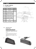
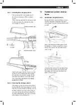
Preparation of the storage box

To protect against damage during transport, 

the storage box is supplied in a closed state 
(Fig.01).

In order to open the box prior to initial use, 
the locking tab must be cut open at the 
marked point with a sharp blade, as shown. 
(Fig.02)

Fig.01

Fig.02

Number

Description

Spare 

part

1

Storage-Box

34096

2

Hydration-Box MY20

34174

3

Magnetic Fit System MY20

4

Hydration Lid MY20

5

Hydration Cap MY20

6

Straw

7

Straw Holder

32765

Summary of Contents for AERIUM C:68/TT

Page 1: ...M C 68 TT AERIUM C 68 TT RAHMENSET AERIUM C 68 TT AERIUM C 68 TT RAHMENSET DEUTSCH GENERAL HANDBOOK CUBE AERIUM C 68 TT AERIUM C 68 TT RFRAMESET AERIUM C 68 TT AERIUM C 68 TT RFRAMESET ENGLISH AB MODELLJAHR 2020 FROM MODEL YEAR 2020 ...

Page 2: ... Allgemeine Information 09 8 2 Vor dem Einbau 09 8 2 1 Montage Demontage der Steckachse 09 10 8 2 2 Montage Demontage einer Schnellspanner Steckachse 10 8 2 3 Montage einer DT SWISS RWS Schnellspanner Steckachse 10 11 9 Cockpit 12 9 1 Übersicht Anbauteile 12 9 2 Cockpit Cable Routing 13 10 Schaltung 13 10 1 Rahmen DI2 Cable Routing 13 11 Sattelstütze Sattel 14 11 1 Übersicht 14 11 2 Montage der Sa...

Page 3: ...BEDIENUNGSANLEITUNG CUBE AERIUM C 68 AERIUM C 68 TT AERIUM C 68 TT RAHMENSET DEUTSCH ...

Page 4: ...tung von rechts links vorne oder hinten die Rede ist bedeutet dies im mer von der Position in Fahrtrichtung aus gesehen 1 1 3 Abkürzungsverzeichnis 1 1 4 Begriffsdefinitionen Achter Eine Rundlaufabweichung an der Felge wird umgangssprachlich als Achter bezeichnet bar Gebräuchliche Einheit für Luft druck 1 Über diese Bedienungsanleitung Drehmoment Auch Anzugsmoment genannt Gibt an wie fest eine Sch...

Page 5: ...hr Rad ausschließlich im dafür vorge gebenen Einsatzbereich Bezeichnung Kompatibilität Steuersatz 11 8 IS42 Top IS42 Bottom Innenlager BB 86 5mm Press Fit 41mm Bremsen Nur kompatibel mit MAGURA RT AERO CUBE TT Leistungsmessung Pineer Quarq SRM SHIMANO power2max Reifen 23mm max 25mm Kettenblatt max 55T Schaltauge 57610 Standart 57611 Direct Schaltung Nur kompatibel mit SHIMANO Di2 SRAM eTap Bike Ei...

Page 6: ...stütze 4 Basislenker HIGH LOW Variante 5 Cover Vorderradbremse 6 Cover Hinterradbremse 7 Vorbau Cover 8 Sitzrohr Cover 9 MAGURA RT Aero Bremsen 10 Di2 Akku Befestigung 11 Schaltauge Standard Direct Mount Variante 12 Steuersatz 13 Sattelklemmung 14 Profile Design Aero Cockpit 15 Storage Box 16 Hydration System 17 Straw Holder ...

Page 7: ...6 AERIUM 5 Anzugsmomente Max Anzugsmomente ...

Page 8: ...utzte Bremsscheiben können die Bremswirkung vermindern Verschmutzte Bremsscheiben müssen um gehend gereinigt werden 1 Ziehen Sie mit Handkraft den Bremssat tel wechselnd in alle Richtungen Der Bremssattel darf sich nicht bewegen 7 Bremsen Laufräder 7 1 Wahl der richtigen Bremsbeläge Gefahr von Personen und Sachschäden Bitte beachten Sie dass Laufräder aus Carbon spezielle Bremsbeläge benötigen Für...

Page 9: ...en Sie jeweils Vorder und Hinterrad hoch und drehen Sie es mit der Hand Die Bremsscheibe darf nur einen kleinen Seitenschlag haben 5 Lassen Sie den Verschleiß der Brems beläge und der Bremsscheibe in einer Fachwerkstatt kontrollieren siehe dazu auch Kapitel 12 Serviceplan Die Bremsbeläge dürfen nicht über den Verschleißindikator abgefahren sein Die Bremsscheibe darf die Mindeststärke nicht untersc...

Page 10: ...stellt werden um den Abstand des Reifens zum Rahmen zu optimieren Stellen Sie sicher dass beide Einstellschrauben gleichmäßig eingestellt sind Kontrollieren Sie den mittigen Sitz des Laufrades zwischen den Kettenstreben Abschließend fixieren Sie das Laufrad indem Sie den Schnellspanner nach der Bedienungsanleitung des Herstellers schließen Gefahr von Personen und Sachschäden Überprüfen Sie vor jed...

Page 11: ... der Steckachse 2 Befestigen Sie die Steckachse handfest mit einem Inbusschlüssel 3 Anschließend fixieren Sie die Steckachse nach den Vorgaben des Herstellers mit einem Drehmomentschlüssel 4 Für den Ausbau müssen sie die Steck achse mit einem Inbusschlüssel heraus schrauben 8 2 2 Montage Demontage einer Schnellspanner Steckachse Gefahr von Personen und Sachschäden Beachten Sie in diesem Zusammenha...

Page 12: ...leichtes herausziehen des Hebels in einer günstigen Position arretiert werden 3 Durch loslassen des RWS Spannhebels rastet dieser dann an der gewünschten Po sition sicher ein Achten Sie auf einen festen Sitz und die geeignete Positionierung des Spannhebels Bitte entnehmen Sie die kor rekte Positionierung und deren Einstellung der Bedienungsanleitung des jeweiligen Schnellspanner Steckachsen Herste...

Page 13: ... die Extension Klemmung 7 Klemmkeil Teil 1 8 Klemmkeil Teil 2 9 Befestigungsbracket 10 Extension 11 Zylindermuttern 12 5mm Sicherheitsbrücke ab 40 mm Spacerhöhe 13 5mm Spacer 14 10mm Spacer 15 20mm Spacer 16 40mm Spacer 17 Unterlegscheiben für Bracket Klemmung 18 Befestigungsschraube für Brackets 19 Vorbauklemmung 9 Cockpit 9 1 Übersicht Anbauteile ...

Page 14: ...3 AERIUM 9 2 Cockpit Cable Routing 350mm to bottom bracket 350mm 50mm 1000mm 10 Schaltung 10 1 Rahmen DI2 Cable Routing 300mm 1000mm 300mm 650mm junction box to rear derailleur Battery to front derailleur ...

Page 15: ...n aussen nur leicht damit die Gewindeplatte nicht in das Sitzrohr fallen kann Im nächsten Schritt kann das magne tische Gegenstück 4 auf die Gewindeplatte im Sitzrohr aufgesteckt werden Die Fixierung der Sattelstütze erfolgt über zwei Schrauben 3 auf der Rückseite des Sitzrohrs Montieren Sie die Schrauben unter Berücksichtigung des vorgegebenen Drehmoments max 5 6 Nm Dadurch wird die Klemmplatte g...

Page 16: ...chtung ein und platzieren diesen auf der Sattelstütze 1 Achten Sie bei der Befestigung des Sattels darauf dass das Gestell des Befestigungs mechanismus der Sattelstütze mittig geklemmt wird Ziehen sie nun den Halte bolzen 1 schrittweise an und stellen Sie sicher dass die Klemmvorrichtung noch exakt auf der Aufnahme der Sattelstütze sitzt und das Sattelgestell von beiden Seiten der Klemme sauber um...

Page 17: ...ngszustand noch geschlossen Abb 01 Um die Box vor dem erstmaligen Gebrauch zu öffnen muss die Verschlusslasche wie abgebildet mit einer scharfen Klinge an der markierten Stelle aufgeschnitten werden Abb 02 Abb 01 Abb 02 Position Beschreibung Einzelteile 1 Storage Box 34096 2 Hydration Box MY20 34174 3 Magnetic Fit System MY20 4 Hydration Lid MY20 5 Hydration Cap MY20 6 Straw 7 Straw Holder 32765 ...

Page 18: ...n Innen auf die Verschlusskappe kann diese entfernt werden um die Innenseiten besser zu erreichen Zur Reinigung verwen den Sie bitte warmes Wasser und Spülmittel Alternativ ist auch eine Reinigung bei max 45 Grad im Geschirrspüler möglich 13 Bedienungsanleitung Hydration System 13 1 Montage der Hydration Box Entfernen Sie das Vorbau Cover indem Sie dieses wie abgebildet anheben bis sich die Magnet...

Page 19: ...ihn fest Achten Sie dabei auf den korrekten Sitz des Verschluss Schiebers an der Einfüllöffnung Zum Abnehmen des Deckels greifen Sie diesen in der Rille an der Vorderkante der Flasche und ziehen sie ihn nach oben ab 13 2 3 Reinigung des Hydration Systems Sämtliche Teile des Hydration Systems sind bis 45 C spülmaschinenfest und können bequem im Geschirrspüler gerei nigt werden Selbstverständlich is...

Page 20: ...te Anbauteile durch modelljahrübergreifende technische Än derungen an Rahmen oder Gabel sind vom Kunden zu tragen 14 2 CUBE CRASH REPLACEMENT CCR Gefahr von Personen und Sachschäden Dieser Austauschservice soll Ihnen nach einem Sturz mit offensichtlichen oder nicht auszuschließenden Schäden an Carbon Rahmen und Gabeln einen unkomplizierten und kostengünstigen Austausch ermöglichen Der Service kann...

Page 21: ...0 AERIUM Stand Dezember 2019 Impressum Hersteller Pending System GmbH Co KG Ludwig Hüttner Straße 5 7 95679 Waldershof Germany www cube eu Info cube eu Aufkleber Rahmenseriennummer am Oberrohr angebracht ...

Page 22: ...M C 68 TT AERIUM C 68 TT RAHMENSET AERIUM C 68 TT AERIUM C 68 TT RAHMENSET DEUTSCH GENERAL HANDBOOK CUBE AERIUM C 68 TT AERIUM C 68 TT RFRAMESET AERIUM C 68 TT AERIUM C 68 TT RFRAMESET ENGLISH AB MODELLJAHR 2020 FROM MODELYEAR 2020 ...

Page 23: ...Operate the thru axle 09 8 1 General information 09 8 2 Before installation 09 8 2 1 Assembling disassembling the thru axle 10 8 2 2 Assembling disassembling a quick release thru axle 10 8 2 3 Assembling a DT SWISS RWS thru axle 11 9 Cockpit 12 9 1 Overview of mounted parts 12 9 2 Cockpit cable routing 13 10 Gears 13 10 1 Frame DI2 cable routing 13 11 Seatpost saddle 14 11 1 Overview 14 11 2 Insta...

Page 24: ...GENERAL HANDBOOK CUBE AERIUM C 68 AERIUM C 68 TT AERIUM C 68 TT RFRAMESET ENGLISH ...

Page 25: ...y stages He is your point of contact for servicing inspec tions modifications and all types of repairs Should you have any questions regarding our product please contact your cycle dealer 1 About this Owner s Manual Run out A radial deviation on the rim is colloquially known as a run out Bar conventional unit for air pressure Torque Also called tightening torque Indicates how tight a screw has bee...

Page 26: ...se note the clas sification of your model Use your bike only in its specified area of application Name Compatibility Headset 11 8 IS42 Top IS42 Bottom Inner bearing BB 86 5mm Press Fit 41mm Brakes Only compatible with MAGURA RT AERO CUBE TT Power meter Pineer Quarq SRM SHIMANO power2max Tyres 23mm max 25mm Chainring max 55T Derailleur hanger 57610 standard 57611 direct Gears Only compatible with S...

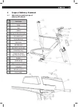
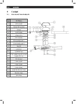
Page 27: ...1 frame 2 fork 3 seatpost 4 basebar HIGH LOW Version 5 front brake cover 6 rear brake cover 7 stem cover 8 seat tube cover 9 MAGURA RT Aero brakes 10 Di2 battery plug 11 hanger standard direct mount version 12 headset 13 saddle clamp 14 profile design aero cockpit 15 storage box 16 hydration system 17 Straw Holder ...

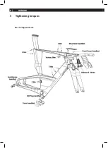
Page 28: ...6 AERIUM 5 Tightening torques Max Anzugsmomente ...

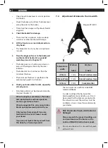
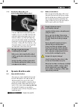
Page 29: ... 7 2 Releasing the hydraulic brakes and removal of wheels Move the locking lever on the brake grip downwards 1 In releasing this the brake callipers open The wheel can now be removed The first time the brake lever is engaged the locking lever automatically returns to the locked position Risk of personal injury and material damage Please research the proper handling use and maintenance of the brake...

Page 30: ...edia tely see Chapter 11 When touring for several days the brake disk brake blocks and brake pads can sustain a great deal of wear When touring like this carry spare brake blocks and replacement pads with you Only replace them yourself if you are familiar with this task Please consult your dealer If you cannot replace them yourself have this done by a trained specialist 7 4 Adjustment of brakes to...

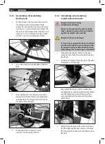
Page 31: ...ger of personal injury and property damage Important information on handling and using thru axles Never use tools besides those recom mended by the manufacturer to attach the axle Always work using a torque wrench Never exceed the maximum torque indicated by the manufacturer Always read the operating manual from the suspension fork or wheelset manu facturer before starting to use a fork wheelset c...

Page 32: ...t the clamping lever is positioned correctly Please see the operating manual from your thru axle manufacturer for the correct position and setting 3 Open the quick release thru axle to remove it After opening the lever you can unscrew the thru axle and remove it completely from the hub 8 2 2 Assembling disassembling a quick release thru axle Danger of personal injury and property damage Always rea...

Page 33: ...retension the system screw in the RWS clamping lever into the thread in a clockwise direction 2 The minimum manual torque which must be applied is 15 Nm The RWS clamping lever can then be locked by softly pulling it into a good position 3 Releasing the RWS clamping lever it will securely lock into the desired position Please ensure that the lever is tight and the clamping lever is positioned corre...

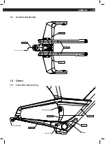
Page 34: ... 6 clamp washer 7 clamp wedge part 1 8 clamp wedge part 2 9 bracket 10 extension 11 cylindrical nut 12 5mm safetey brige for spacer heights 40 mm 13 5mm spacer 14 10mm spacer 15 20mm spacer 16 40mm spacer 17 washer for bracket screws 18 bracket screws 19 tem clamp 9 Cockpit 9 1 Overview of mounted parts ...

Page 35: ... 13 AERIUM 9 2 Cockpit Cable Routing 350mm to bottom bracket 350mm 50mm 1000mm 10 Gears 10 1 Frame DI2 cable routing 300mm 1000mm 300mm 650mm junction box to rear derailleur Battery to front derailleur ...

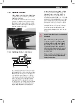
Page 36: ...crews 3 from the outside so that the threaded plate cannot fall into the seat tube Now the magnetic counterpart 4 can be attached to the threaded plate in the seat tube The seatpost is fixed into place via two screws 3 on the rear of the seat tube Install the screws taking into account the specified torque maximum of 5 6 Nm As a result the clamping plate is pressed against the seatpost and allows ...

Page 37: ... put the saddle in the clamp ing device and place it on the seatpost 1 When affixing the saddle check that the mounting mechanism of the seatpost is clamped in the middle Now gradually tighten the retaining pin 1 and make sure that the clamping device is still sitting precisely in its correct location on the seat post and that the saddle frame is equally gripped by from both sides of the clamp Fin...

Page 38: ... storage box is supplied in a closed state Fig 01 In order to open the box prior to initial use the locking tab must be cut open at the marked point with a sharp blade as shown Fig 02 Fig 01 Fig 02 Number Description Spare part 1 Storage Box 34096 2 Hydration Box MY20 34174 3 Magnetic Fit System MY20 4 Hydration Lid MY20 5 Hydration Cap MY20 6 Straw 7 Straw Holder 32765 ...

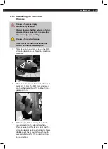
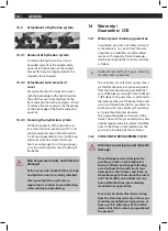
Page 39: ...om the top tube for cleaning purposes Pressure from the inside will remove the cap so as to be able to better reach the interior Please use warm water and washing up liquid for washing Alternatively wash at a maximum of 45 degrees in the dishwasher 13 Hydration system instruc tions 13 1 Installation of hydration box Remove the front cover by lifting as shown until the magnetic connection has been ...

Page 40: ...y on all products i e 2 years from the date of purchase In addition we offer added service with respect to frame breakages which goes beyond the statutory warranty as follows Carbon frames and forks 3 years voluntary manufacturer s guarantee This voluntary manufacturer s guarantee is granted for the above mentioned period from the date of purchase provided that your CUBE bike was bought from an of...

Page 41: ...property damage The manufacturer is not responsible and cannot be held liable for accidents and inju ries caused by improper use or disregard for the instruction manual incorrect adjust ments or by neglect or excessive wear ...

Page 42: ...9 Company details Manufacturer Pending System GmbH Co KG Ludwig Hüttner Straße 5 7 95679 Waldershof Germany www cube eu Info cube eu FON 49 0 9231 97 007 80 FAX 49 0 9231 97 007 199 Sticker frame serial number attached to top tube ...

Reviews: