10
11
ASSEMBLY INSTRUCTIONS
ASSEMBLY INSTRUCTIONS
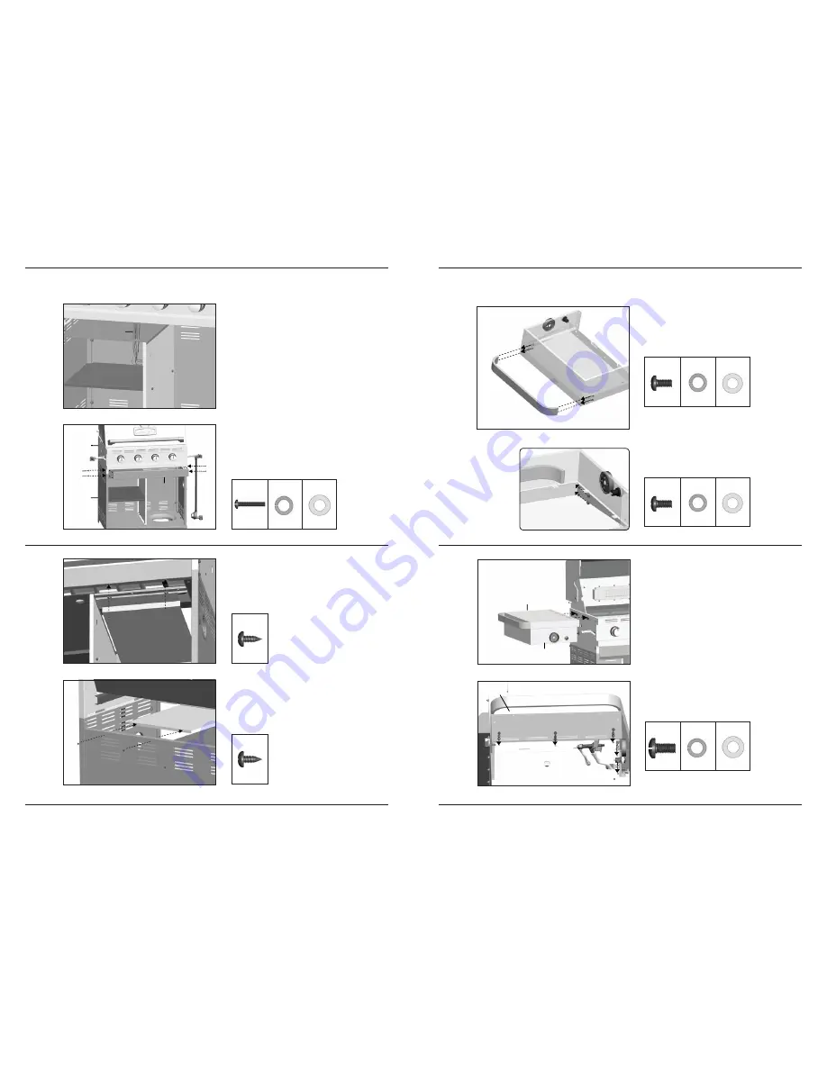
7.
b. Remove Electrode Wires (CG) from Manifold
Assembly (CA), and feed the wires through
the hole in Left Heat Shield (CS), as shown in
figure B.
c. Assemble the Front Brace (CK) to the Burner
Box and Cart Assembly (B + C), as shown in
figure C.
8.
Front, left side view
Front view
b. Assemble the Right Heat Shield (CP) to
the Lower Back Panel (CO), as shown in
figure B.
a. Assemble the front of the Right Heat Shield
(CP) to the Front Brace (CK), as shown in
figure A.
B
C
A
CP
CK
a. Assemble a Towel Bar (DI) to the Left Side
Shelf Table (DL), as shown.
b. Repeat for the Right Side Shelf Table (DA).
9.
10.
6
6
X 4
X 5
X 4
X 5
X 4
X 5
YOU WILL NEED:
YOU WILL NEED:
1
2
3
3
4
4
Back view
B
CP
CO
6
6
X 2
X 2
YOU WILL NEED:
YOU WILL NEED:
12
12
6
6
X 4
X 4
X 4
X 4
X 4
X 4
YOU WILL NEED:
YOU WILL NEED:
5
5
7
7
8
8
Front, left side view
View under left side shelf
a. Assemble the Left Side Shelf Assembly
(DL and DM) to the Cart Assembly by
inserting the Side Shelf tabs into the holes on
the Cart Assembly (figure A).
b. Secure using hardware, as shown in figure B.
A
B
DL
DM
CK
CS
CQ
DL
C
A+B
CG
Close up
B
A


