background image

M5 x 8 mm Bolt

(x3)

DD

ASSEMBLY INSTRUCTIONS

9

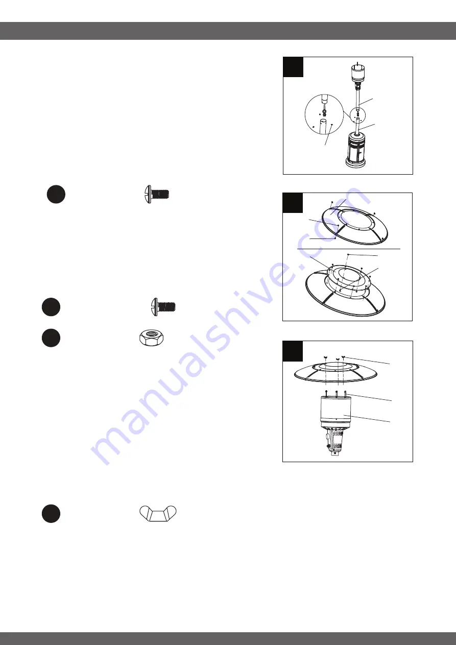
STEP 7

-------------------------------------------

Feed the valve and gas hose and connect Upper Pole (D) 
to the Lower Pole Assembly (F).

Feed the valve and gas hose into and go through the 
Lower Pole Assembly

Screw Upper Pole (D) onto Lower Pole Assembly (F) until 
the holes on Upper Pole (D) is aligned to the holes on top 
of Lower Pole Assembly (F). Fix them by using three M5 x 
8 mm Bolts (DD). Ensure they are fully tightened. 

STEP 8

-------------------------------------------

Attach the four KD Domes (B) using M5 x 8 mm Silver 
Bolts (FF) and M5 Nuts (GG). Then, complete dome 
assembly by attaching Top Dome (A) to KD Domes (B) 
with M5 x 8 mm Silver Bolts (FF) and M5 Nuts (GG).

STEP 9

-------------------------------------------

Attach dome assembly to Burner Assembly (C) by
securing wing nuts (KK) to Reflector Spacers (BB).

Take out the AAA-battery included in
the pack with instruction manual.

Insert the AAA-battery to the igniter.

Screw the igniter cap back clockwise. 

DD

F

D

B

GG

FF

A

GG
FF

BB

C

KK

7

8

9

M5 x 8 mm Silver Bolt

(x12)

FF

M5 Nut

(x12)

GG

Wing Nut

(x3)

II

Summary of Contents for COH-300

Page 1: ...NG Do not store or use gasoline or other flammable vapors and liquids in the vicinity of this or any other appliance An LP cylinder not connected for use shall not be stored in the vicinity of this or...

Page 2: ...ng 14 Replacement Part List 15 Warranty 16 Certification CSA Height Overall 86 6 inches Reflector Diameter 31 50 inches Rated Heat Input 48 000 BTU HR Fuel Propane LP Gas Supply 20 Lb LP Gas cylinder...

Page 3: ...installed Fix the base on an incline no wider than 15 degrees 5 Place the propane hose with regulator assembly out of pathways where people may trip over it or in areas where the hose will not be subj...

Page 4: ...0 The cylinder used must include a collar to protect the cylinder valve 21 Do not store a spare LP gas cylinder under or near this appliance 22 Never fill the cylinder beyond 80 percent full 23 Place...

Page 5: ...Description Quantity A Top Dome 1 pc B KD Dome 1 pcs C Burner Assembly 1 pc D Upper Pole 1 pc E Beauty Ring 1 pc F Lower Pole Assembly 1 pc G Cylinder Housing Assembly 1 pc H Base 1 pc I Wheel Assembl...

Page 6: ...15 mm Bolt Reflector Spacer M8 Nut M5 x 8 mm Bolt M6 x 10 mm Bolt M5 x 8 mm Silver Bolt M5 Nut AAA Battery Wing Nut BB x3 x2 x12 x4 x16 x2 x1 x12 x3 AA CC DD EE FF GG HH II Shroud Fix Bracket x5 JJ H...

Page 7: ...d be on the opposite side of the wheel assembly I M5 x 8 mm Bolt x5 DD ASSEMBLY PREPARATION ASSEMBLY INSTRUCTIONS 7 Before beginning assembly of product make sure all parts are present Compare parts w...

Page 8: ...y C to the Upper Pole D Feed the valve and gas hose into and go through the Upper Pole D Align the screw holes and secure Burner Assembly C onto Upper Pole D with M5 x 8 mm Bolts DD Notes a Open the i...

Page 9: ...m Bolts DD Ensure they are fully tightened STEP 8 Attach the four KD Domes B using M5 x 8 mm Silver Bolts FF and M5 Nuts GG Then complete dome assembly by attaching Top Dome A to KD Domes B with M5 x...

Page 10: ...make sure the cylinder valve is OFF Then turn the knob on the regulator counterclockwise until it is loose Warning Before connecting be sure that there is no debris caught in the head of the LP gas cy...

Page 11: ...tank valve ON 4 Push control knob in and slowly rotate to HIGH This will activate the built in igniter and light the burner Once burner is lit hold control knob in for 30 seconds and then release If t...

Page 12: ...equired as necessary It is imperative that control compartment burners and circulating air passageways of the heater be kept clean Spiders and insects can create a dangerous condition that may damage...

Page 13: ...air passageways clean Signs of possible blockage include Gas odor with extreme yellow tipping of flame Heater does NOT reach the desired temperature Heater glow is excessively uneven Heater makes pop...

Page 14: ...The control knob is not positioned at High The burner jet may be partially blocked Outdoor temperature is less than 40 F and tank is less than 1 4 full Supply hose is bent or kinked Turn tank valve OF...

Page 15: ...ly C2 Insulation Plate C3 Control Panel C4 Knob C5 Igniter C6 Thermocouple C7 Ignition Pin C8 Tilt Switch D Upper Pole E Beauty Ring F Lower Pole Assembly G Cylinder Housing Assembly H Shroud Fix Brac...

Page 16: ...allation by the consumer Defects or damage caused by the use of other than genuine parts are not covered by this warranty This warranty shall be effective from the date of purchase as shown in the pur...

Reviews: