Navigating the Menus and Keypad
20
19
CULLIGAN GLOBAL ELECTRONIC CONTROLLER
Navigating the Menus and Keypad
system ok
9:17 am 1-17-08
> 1) information
2) bypass
3) regenerate
4) set time and date
1) information
> 2) bypass
3) regenerate
4) set time and date
1) information
2) bypass
> 3) regenerate
4) set time and date
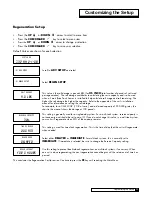
regeneration
off
regeneration
>
off
regeneration
>
now
regeneration
> tonite
regeneration
tonite
> 1) information
2) bypass
3) regenerate
4) set time and date
regeneration tonite
9:18 Am 1-17-08
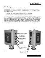
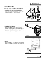
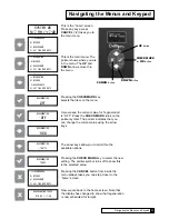
This is the “home” screen.
Press any key except
CANCEL
(“
x
”) takes you to
the main menu.
This is the main menu. The
pointer shows where you are
in the menu. The
UP
and
DOWN
arrows move thru
the menu.
Pressing the
CHECKMARK
key
selects that item on the menu.
Here we see the current value for “regeneration”
is “OFF”. Press the
CHECK MARK
turns on the
pointer symbol. The pointer indicates that you
can change the current value using the arrow
keys.
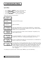
The arrow keys allow you to scroll thru the
available options.
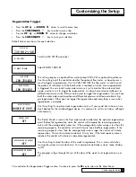
Pressing the
CHECK MARK
key to select the new
setting. The pointer symbol turns off to show this
is the selected value.
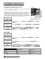
Pressing the
CANCEL
button from inside the
menu always takes you one step closer to the
“home” screen.
Now we are back to the home screen. Note that
the display has changed to show that regeneration
is now scheduled for tonight.
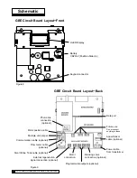
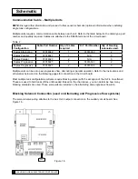
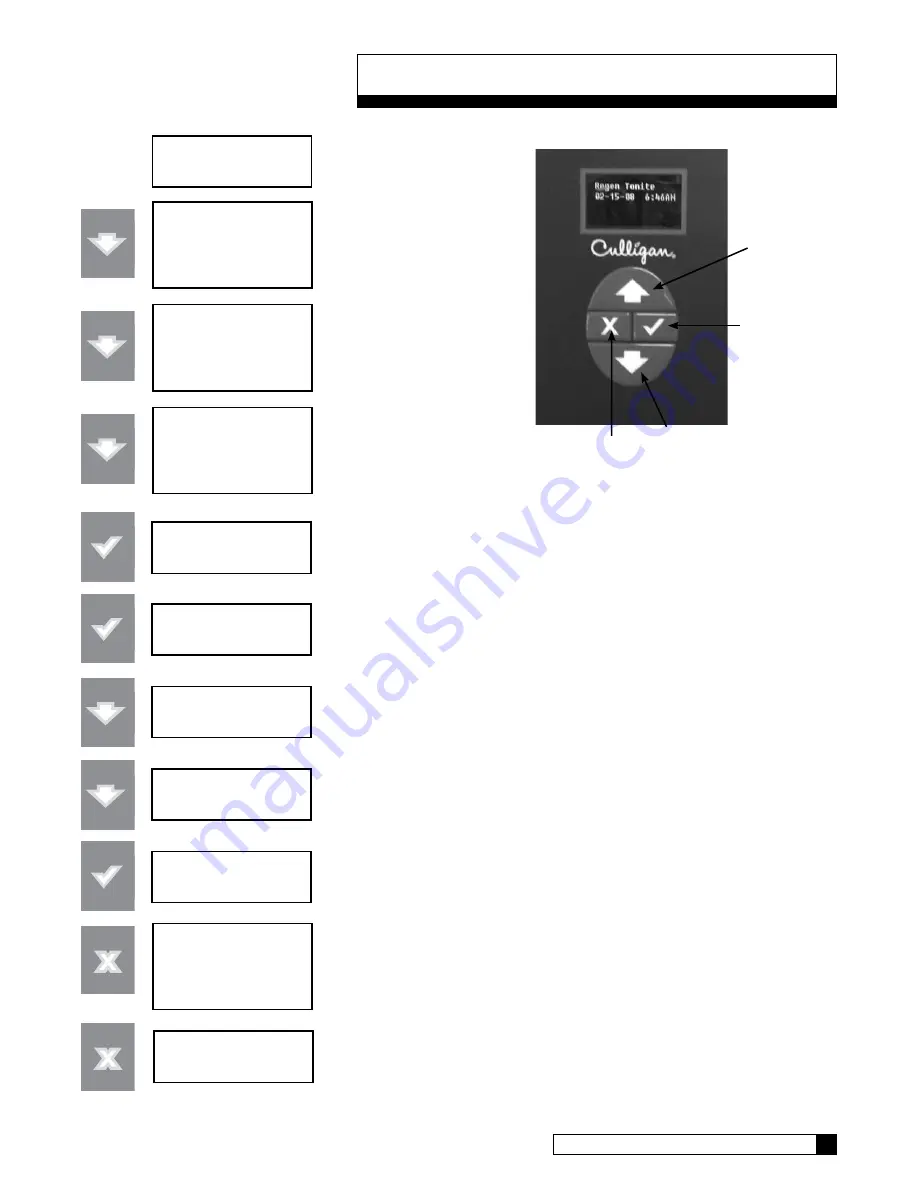
DOWN
button
CHECK MARK
or
OK
button
UP
button
CANCEL
button
Summary of Contents for GBE
Page 62: ...Menu Overview Continued on page 61 59 CULLIGAN GLOBAL ELECTRONIC CONTROLLER ...
Page 63: ...Menu Overview Menu Overview 60 ...
Page 64: ...Menu Overview Continued from page 59 61 CULLIGAN GLOBAL ELECTRONIC CONTROLLER ...
Page 65: ...Menu Overview Menu Overview 62 ...
Page 72: ...Appendix D 69 CULLIGAN GLOBAL ELECTRONIC CONTROLLER ...


