background image

INSTALLATION AND OPERATION MANUAL

MF3700, MF3800 Models

Page 4

800-345-6007

CumberlandStoveWorks.com

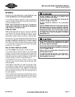
VENT TERMINATION CLEARANCES

CLEARANCE

4 feet

Clearance below or beside any door or window 

that opens.

1 foot

Clearance  above  any  door  or  window  that 

opens.

3 feet

Clearance from any adjacent building.

7 feet

Clearance from any grade when adjacent to 

public walkways.

2 feet

Clearance above any grass, plants, or other 

combustible materials.

3 feet

Clearance from any forced air intake of any 

appliance.

2 feet

Clearance below eaves or overhang.

1 foot

Clearance  horizontally  from  combustible 

wall.

3 feet

Clearance above the roof.

2 feet

Clearance above the highest point on the roof 

within 10 feet.

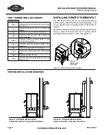
VENTING INSTALLATION EXAMPLES

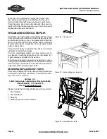
Figure 0:  STRAIGHT INSTALLATION
Inside Vertical Rise, Horizontal Termination

Figure 9: STRAIGHT INSTALLATION
Outside Vertical Rise, Through Wall Installation

INSTALLING REMOTE THERMOSTAT

The  MF  Parlor  Stove  can  be  run  thermostatically  by 

purchasing any milivolt thermostat (sold separately).  This 

step is optional and not required for MF Parlor Stove to 

operate.
Mount thermostat according to manufacturer specifications.    

Using  a  small  flat  head  screw  driver,  tighten  remote 

thermostat wires into pins 7 and 8.  See figure 18.

remote

thermostat 

terminals

Figure 18: Remote Thermostat Terminals

Summary of Contents for MF3700

Page 1: ...xternal part starts to glow you are overfiring Reduce feed rate Overfiring will void the warranty Comply with all minimum clearances to combustibles as specified Failure to comply may cause a house fire WARNING HOT DO NOT TOUCH SEVERE BURNS MAY RESULT CLOTHING IGNITION MAY RESULT Glass and other surfaces are hot during operation and cool down Keep children away CAREFULLY SUPERVISE children in same...

Page 2: ......
Page 3: ...1 Clearance to Combustibles 12 Venting 13 Type of Vent 13 Pellet Vent Installation 13 Vent Termination Clearances 14 Venting Installation Examples 14 Installing RemoteThermostat 14 Outside Air Connection 15 Mobile Home 15 Operating Instructions 15 Understanding the TRI X Controller 15 Operating Stove 16 Fuel Range Selection 17 Starting Fire and Electric Ignite Screens 17 Thermostat control options...

Page 4: ...three year warranty program Our fire pots and labor are also covered under the three year warranty THIS WARRANTY IS LIMITED TO DEFECTIVE PARTS REPAIR AND OR REPLACEMENT AT ARDISAM INC S OPTION AND EXCLUDES ANY INCIDENTAL AND CONSEQUENTIAL DAMAGES CONNECTED THEREWITH This warranty is not transferable and supersedes all other warranties either expressed or implied and all other obligations to liabil...

Page 5: ...ce Fill out and mail the registration card located in the parts packet or register online at www cumberlandstoveworks com Warranty is valid only if the completed registration is received by Ardisam Inc within 30 days of purchase OWNERSHIP RECORDS Dealer s Name Dealer s Address City State Province Zip Code Postal Code Model Number Serial Number Date of Purchase Notes SERVICE DATE SERVICE TECHNICIAN...

Page 6: ... area or any location that can build up a concentration of fumes such as a stairwell covered breezeway etc caution INDICATES A HAZARD WHICH IF NOT AVOIDED MIGHT RESULT IN MINOR OR MODERATE INJURY AND PROPERTY DAMAGE Proper installation of this stove is necessary for safe and efficient operation Installing this product improperly may result in a house fire and personal injury All applicable buildin...

Page 7: ...n of the room accompanying the parlor stove If not the pressure switch may shut off operation of the parlor stove The moving parts of this stove are propelled by high torque electric motors These parts can cause severe damage to body parts that get near them Keep all body parts away from auger and fans while the stove is plugged into an electrical outlet These moving parts may begin to move at any...

Page 8: ...right from the field Damage caused by dirty corn is not covered by the product warranty Ask for screened corn only Stalk parts excessive fines and cob remnants will clog the air flow holes in burn plate Check the corn for foreign objects Store the corn supply in a dry place and keep the bags or container sealed to prevent it from absorbing excess moisture Test the moisture content periodically to ...

Page 9: ... quality You may have to screen each bag of pellets if dust becomes a problem Wood pellets are generally produced out of wood waste such as sawdust and shavings The raw material is dried mechanically fractioned to size and extruded under intense pressure into pellets Wood pellets need to be protected from direct water penetration If exposed to water droplets from condensation they will gradually d...

Page 10: ... Based on post 1982 home construction requiring 35 BTU Hr per Sq Ft 3 Install per NFPA 70 and follow all state and local codes contact licensed electrical contractor for assistance 4 Install per NFPA 211 and follow all state and local codes contact licensed installers for assistance Listing label Tested to the following stardards UL1482 ASTM E1509 ULC ORD C1482 M1990 GLASS SPECIFICATIONS This stov...

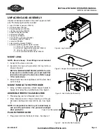
Page 11: ...ve on its side 2 Assemble the legs using provided 12 leg bolts as shown in figure 4 NOTE for mobile home installation If unit is to be used in a mobile home you must install the 4 tie down straps to the stove now Refer to page 15 for instructions 3 After all bolts have been tightened set the stove back up on its legs MOUNT HANDLE TO HOPPER DOOR 1 Using a Phillips screwdriver attach hopper handle t...

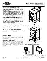
Page 12: ...he 4 self tapping screws 2 through the plastic bracket and 2 through the back panel of the stove Attach through the pre drilled holes Note Self tapping screws must penetrate hopper 2 Back of the stove with controller hidden You may mount the controller on either side of the stove see figure 9 So it is not visible during operation Attach the plastic mounting bracket to the pre drilled holes on eith...

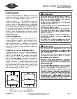
Page 13: ...r of t vent See figure 12 When stove is vented straight through the wall and the clean out t vent is on the exterior of the home the minimum clearance is 3 from the back of the stove to the edge of floor protector See figure 13 The minimum floor protector material is 24 GA sheet metal warning READ THIS ENTIRE MANUAL BEFORE YOU INSTALL AND USE THIS STOVE fAILURE TO FOLLOW THE INSTRUCTIONS MAY RESUL...

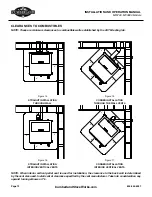
Page 14: ...t is used for installation the clearance to the back wall is determined by the vent size used Install vent at clearance specified by the vent manufacturer Take into consideration any upward turning elbows or T s CORNER INSTALLATION Interior Vertical Vents STRAIGHT INSTALLATION Through Wall 3 4 6 4 CORNER INSTALLATION Through the Wall Vents STRAIGHT INSTALLATION INTERIOR VERTICAL VENTS Figure 14 Fi...

Page 15: ...sance or hazard from exposing people or shrubs to high temperatures The installation must include a clean out tee to enable collection of fly ash and to permit periodic cleaning of the exhaust system Total length of horizontal vent must not exceed 10 feet The maximum recommended vertical venting height is 18 feet All joints for pellet vent are required to be fastened with at least three screws and...

Page 16: ...ance horizontally from combustible wall 3 feet Clearance above the roof 2 feet Clearance above the highest point on the roof within 10 feet VENTING INSTALLATION EXAMPLES Figure 20 STRAIGHT INSTALLATION Inside Vertical Rise Horizontal Termination Figure 19 STRAIGHT INSTALLATION Outside Vertical Rise Through Wall Installation Installing REMOTE Thermostat The MF Parlor Stove can be run thermostatical...

Page 17: ...e air source 3 Stove must be electrically grounded to the steel chassis of the mobile home 4 All vertical chimney vents must have wall supports 5 All exhaust systems must have a spark arrestor WARNING DO NOT CONNECT TO ANY AIR DISTRIBUTION DUCT OR SYSTEM do not install in a sleeping room Figure 21 Mobile Home Anchor Leg Assembly CAUTION THE OPERATION OF EXHAUST FANS SUCH AS BATHROOM FANS ATTIC FAN...

Page 18: ... light the fire MF3700 stove controllers will read as follows LIGHT FIRE PUSH ON BUTTON Stoves equipped with electric ignition model MF3800 will have the option of starting the fire manually or automatically with the igniter The screen will read as follows electric ignite no yes Pushing SCROLL will send the controller to the LIGHT FIRE PUSH ON BUTTON See Manual Lighting Instructions before startin...

Page 19: ...N buttons During starting fire and electric ignition sequences you may choose to run your stove thermostatically by pressing the THERMOSTAT ON OFF button See Thermostatic Control Operation At any time you may add more fuel to the firepot by pressing the ADD FUEL button Note the feed auger will stay on for one minute or until the ADD FUEL button is pressed again During starting fire and electric ig...

Page 20: ...s mode the screen will display for example the following remote temp 72 range 3 level 4 NOTE The asterick indicates that the termostat is calling for heat To turn off the thermostat mode press the thermostat button until the following screen is displayed tstat off This will return the stove to manual operation where the heat level is controlled by using the Temp Up and Temp Down buttons At anytime...

Page 21: ...g so will cause combustion blower to stop and smoke will enter the room through air intake holes NORMAL CARE MAINTENANCE CLEANING THE GLASS Only clean glass when the glass is cool Wipe the glass clean with a dry or damp rag If this does not clean the glass use any non abrasive liquid spray REMOVAL OF BROKEN CERAMIC GLASS Open the door and lift it from the hinges Lay the door down on newspaper with...

Page 22: ...ut Do not strike glass Do not use abrasive cleaners Do not clean HOT glass replace CERAMIC GLASS WITH factory Authorized REPLACEMENT PARTS ONLY tHE CLINKER WILL REMAIN HOT FOR SEVERAL MINUTES AFTER IT IS PULLED OUT OF THE Fire POT Figure 24 Air filter placement AIR FILTER AIR FILTER Replace air filter annually Replacement filters can be ordered through your stove dealer ...

Page 23: ...e exhaust system will depend upon the ash and debris content of your fuel If your fuel has a high ash content and or significant debris in it the exhaust system will require weekly cleaning Cleaner fuels will allow for monthly cleaning of the exhaust system Clean out tees in the exhaust system make this task much easier NOTE A clean unit burns efficiently and will remain trouble free MONTHLY MAINT...

Page 24: ...ns in the troubleshooting guide in this section The guide will help you pinpoint the causes of common problems and identify remedies For more complicated repairs you may want to rely on your retailer an authorized service center or Ardisam Inc A parts catalog is included in this section We will always be glad to answer any questions you have or help you find suitable assistance To order parts or i...

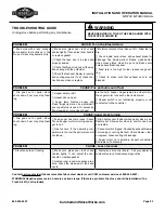
Page 25: ...dust corn cobs or husk are found in hopper Auger jams are evident when the auger motor runs but no fuel is delivered Hopper switch is not functioning properly or not conntected to the controller Problem CAUSE Auger stops turning Fire goes out or parlor stove shuts down Fuel may stop feed ing Feed auger has come loose Check to see if auger motor is turning and au ger is not Heat sensor If the opera...

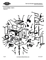
Page 26: ...MF3800 Models Page 24 800 345 6007 CumberlandStoveWorks com MAIN ASSEMBLY PARTS Figure 29 41 24 51 17 36 49 47 35 43 37 11 50 10 33 12 29 25 5 23 46 48 4 16 39 14 34 22 57 53 21 18 1 6 13 8 3 20 28 27 9 52 32 38 7 30 19 15 2 39 61 59 62 42 40 ...

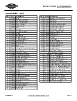
Page 27: ...LOWER 35 720072 AIR PUMP 36 700257 CIRCULATING AIR DUCT 37 710108 AUGER ASSEMBLY 38 700286 SPRING CLIP 39 700269 SIDE PANEL KEY PART DESCRIPTION 40 710116 IGNITER PLUG 3700 ONLY 41 710097 STOVE TOP 42 710098 FIREPLATE 43 730067 OUTBOARD AUGER GASKET 44 720015 PROOF OF FIRE SWITCH 46 700349 CONTROLLER BRACKET 47 730054 IM INTERFACE MODULE 48 730053 PIM CASE AND BRACKET 49 700368 AIR PUMP PLATE 50 7...

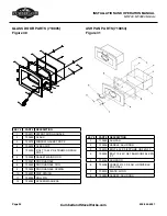
Page 28: ...351 DOOR HANDLE 8 700359 DOOR HANDLE COG 9 720009 DOOR HANDLE SPRING 10 725023 DISC SPRING 11 725026 ROLL PIN 12 725024 SPACER WASHERS GLASS DOOR PARTS 710095 Figure 30 3 2 5 4 8 11 12 10 7 9 1 6 Y ASH PAN PARTS 710053 Figure 31 KEY PART DESCRIPTION 1 710099 ASH PAN 2 730006 HANDLE ASH DOOR 3 725012 BOLT 8 32 X 3 8 PPHMS GR2 ZN F T 4 725000 BOLT 10 24 X 3 8 TBHMS GR2 BLK ZN F T 5 700146 ASH DOOR 6...

Page 29: ...XHAUST PARTS 710105 Figure 32 KEY PART DESCRIPTION 1 710103 EXHAUST MANIFOLD 2 720005 BLOWER COMBUSTION 3 720050 SWITCH ROLLOUT LIMIT 4 720015 SWITCH SNAP DISC 5 509 BOLT 1 4 20 X 1 2 SLHWH ZN F T T C 6 725014 SCREW 6 20 X 3 4 SHHSD ZN 7 725007 SCREW 10 X 3 8 SLHH ZN 8 720056 SQUARE TO ROUND TRANSITION ...

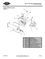
Page 30: ...ER PARTS 710108 Figure 33 KEY PART DESCRIPTION 1 710101 AUGER HOUSING 2 700243 TORQUE ARM 3 730022 AUGER BUSHING 4 700025 INBOARD AUGER PLATE 5 K1038 SET SCREW 6 720079 GEAR MOTOR 7 700033 AUGER COLLAR 8 509 BOLT 9 730015 GASKET INBOARD AUGER 10 710009 AUGER 11 720085 LIMIT SWITCH 1 10 2 6 7 5 8 3 4 9 11 ...

Page 31: ...LINE IN TO EXTERNAL THERMOSTAT LINE IN TO EXTERNAL THERMOSTAT BLACK WHITE BLUE ORANGE YELLOW RED AUGER MOTOR COMBUSTION BLOWER AIR PUMP CONVECTION BLOWER HEAT TORCH HOPPER SWITCH V A C U U M SWITCH IM PMI P R O O F O F FIRE SWITCH OVERTEMP SWITCH AUGEROVERTEMP SWITCH BLACK WHITE BLACK WHITE white black BLACK WHITE BLACK white ...

Page 32: ... of Ardisam Inc 1360 First Avenue P O Box 666 Cumberland Wisconsin 54829 800 345 6007 Fax 715 822 2223 E mail info ardisam com ARDISAM com Visit www ardisam com and discover more innovations that will benefit you throughout the year ...

Reviews: