Super Saver Bunsen Jet Brooder with SPI
5
3.
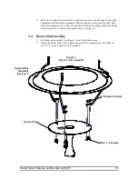
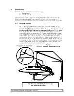
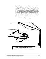
Rotate the suspension rod until the swaged portion mates with the opening, push the
suspension rod through the opening so that the opening is between the swage, then
rotate the suspension rod so that it is positioned with the mounting pedestals pointing
inwards toward the center of the support ring, as in Figure 3.
5.3.
Burner Unit Assembly
1.
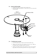
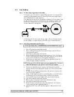
For burner unit assembly, see Figure 3, then follow these steps.
2.
Attach the burner plate to the support ring assembly’s suspension rod with the six
8-32 X 1/2” screws and 8-32 nuts provided.
Support Ring
Assembly
(See Fig. 1)
Figure 3
Burner Unit Assembly
8/32 Kep Lock Nuts
8/32 x 1/2 Screws
Burner Plate

