I
N S T A L L A T I O N
M360-4-GB
- 12 -
3.7 Hydraulic
connections
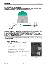
The installation of the humidifier also needs the water supply and drainage pipes to be connected. The pipes, standard supplied, must be
connected to the machine as explained in par. 3.2
Preliminary operations
, on page 5 of this manual.
Fig. 16
The supply pipe A, standard supplied, has a threaded bushing G 3/4 at its two ends: connect the free end (the straight one) directly to a water
tap B, or to an extension. It is advisable to install a mechanical filter C down-line of the tap B, as shown in Fig. 16.
For the water drain use the plastic pipe D, standard supplied, or a one that is similar having a 10-mm internal diameter. The pipe must be
installed as shown in Fig. 16 with a minimum slope of 10°, to guarantee the correct drainage of the water. An eventual siphon E must be on the
main drain and not on the drainpipe connected to the machine.
To guarantee regular drainage of the water, make sure that the drainpipe has a slope and is straight, without any
bends or constrictions.
3.8 Final
operations
•
Make sure that all the wires are positioned properly inside the machine as
shown in Fig. 15.
•
Check that the wiring box is properly closed and positioned correctly in its
lodging, and the spring tightened. The box must have the surface of the cover
resting on the two surface locators as pointed out in
•
Fig. 17
•
Put back the air filter and tighten the three supporting screws.
•
Direct the outlets. To do this, loosen the screws that hold the diffuser 5 of Fig. 2
and that is found on top of the machine, and turn the diffuser: at the end of the
operation block the screw again.
•
Check that the hydraulic connections have been carried out correctly. Open the
water supply tap and check that there are no leaks along the supply circuit
Fig. 17
Summary of Contents for NEB 6500
Page 1: ......
Page 2: ......
Page 3: ...Italiano ...
Page 23: ...English ...
Page 43: ...Español ...
Page 63: ...Français ...
Page 83: ......


