background image

18

Key No. Qty.

Description

Key No. Qty.

Description

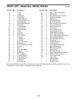
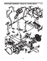
PART LIST—Model No. AEVEL19008.0

R1009A

1

1

Frame

2

1

Upright

3

1

Left Shield

4

1

Right Shield

5

2

Upper Body Leg

6

1

Left Upper Body Arm

7

1

Idler Assembly

8

1

Right Upper Body Arm

9

2

Disc Cover

10

1

Front Stabilizer

11

1

Left Pedal Arm

12

1

Right Pedal Arm

13

2

Pedal

14

2

Axle Cap

15

2

Pedal Disc

16

2

Disc Crossbar

17

1

Flywheel

18

1

Incline Motor

19

1

Drive Belt

20

1

Resistance Cable

21

4

Stabilizer Cap

22

2

M10 x 25mm Patch Screw

23

1

Console

24

2

Grip

25

1

M6 x 16mm Bolt

26

1

Magnet

27

5

M6 Locknut

28

1

Rear Stabilizer

29

2

Flywheel Bearing

30

2

Large Snap Ring

31

2

Large Bearing

32

1

Pedal Axle

33

7

M10 Locknut

34

4

M10 x 70mm Carriage Bolt

35

2

M10 Washer

36

4

M6 x 48mm Flat Head Screw

37

2

Pedal Arm Bushing

38

1

M8 Locknut

39

2

M10 Small Washer

40

2

Pedal Arm Bolt Set

41

1

M8 x 22mm Flat Head Screw

42

9

M4 x 16mm Screw

43

4

M6 x 12mm Screw

44

1

Upper Wire

45

4

M4 x 12mm Screws

46

2

Upper Body Arm Cap

47

2

Upper Body Arm Spacer

48

2

M10 x 68mm Button Bolt

49

4

Small Upper Body Arm Bushing

50

4

M6 x 36mm Button Bolt

51

8

M4 x 30mm Button Screw

52

4

M4 Washer

53

1

Reed Switch/Wire

54

1

Cable Clamp

55

2

Inner Pedal Arm Bushing

56

2

M4 x 25mm Screw

57

1

M10 Flat Head Bolt

58

2

Wave Washer

59

2

M10 Split Washer

60

4

Large Upper Body Arm Bushing

61

2

5/16" x 25.4mm Hex Bolt

62

1

M10 x 60mm Bolt

63

1

Lower Wire

*

Grease Packet

*

Assembly Tool

*

Userʼs Manual

Note: Specifications are subject to change without notice. For information about ordering replacement parts, see

the back cover of this manual. *These parts are not illustrated.

Summary of Contents for X-POWER E200

Page 1: ...ial No Write the serial number in the space above for reference www iconeurope com QUESTIONS If you have questions or if there are missing parts please contact us Call 08457 089 009 From Ireland 053 92 36102 Website www iconsupport eu E mail Visit www iconsupport eu Write ICON Health Fitness Ltd c o HI Group PLC Express Way Whitwood West Yorkshire WF10 5QJ UK USER S MANUAL ...

Page 2: ...5 EXERCISE GUIDELINES 16 PART LIST 18 EXPLODED DRAWING 19 ORDERING REPLACEMENT PARTS Back Cover 2 WARNING DECAL PLACEMENT This drawing shows the location s of the warning decal s If a decal is missing or illegible see the front cover of this manual and request a free replacement decal Apply the decal in the location shown Note The decal s may not be shown at actual size ...

Page 3: ...at least 3 ft 0 9 m of clearance in the front and rear of your elliptical exerciser and 2 ft 0 6 m on each side 6 Inspect and properly tighten all parts regu larly Replace any worn parts immediately 7 Keep children under age 12 and pets away from the elliptical exerciser at all times 8 The elliptical exerciser should not be used by persons weighing more than 250 lbs 113 kg 9 Wear appropriate exerc...

Page 4: ...u use the elliptical exerciser If you have ques tions after reading this manual please see the front cover of this manual To help us assist you note the product model number and serial number before con tacting us The model number and the location of the serial number decal are shown on the front cover of this manual Before reading further please familiarize yourself with the parts that are labele...

Page 5: ... area and remove the packing materials Do not dispose of the packing materials until assembly is completed In addition to the included tool s assembly requires an adjustable wrench a Phillips screwdriver a rubber mallet and pliers Use the drawings below to identify the small parts used for assembly The number in parentheses below each drawing is the key number of the part from the PART LIST near t...

Page 6: ...atteries Otherwise you may damage the console displays or other electronic compo nents Remove the battery cover insert the batteries into the battery compartment and reattach the battery cover Make sure to orient the batteries as shown by the diagram inside the battery compartment 1 Identify the Front Stabilizer 10 which is nar rower than the Rear Stabilizer not shown While another person lifts th...

Page 7: ...onto the Frame 1 Attach the Upright 2 with two M10 x 68mm Button Bolts 48 two M10 Split Washers 59 and two M10 Locknuts 33 Do not tighten the Button Bolts yet 4 While another person holds the Console 23 near the Upright 2 connect the console wire to the Upper Wire 44 Then insert the wires into the Upright Tip Avoid pinching the wires Attach the Console 23 to the Upright 2 with four M6 x 12mm Screw...

Page 8: ...2 Make sure that there are two Small Upper Body Arm Bushings 49 in the Left Upper Body Arm 6 Slide an Upper Body Arm Spacer 47 and the Left Upper Body Arm 6 onto the left axle on the Upright 2 Make sure that the Upper Body Arm Spacer is turned so that the curved side faces the Upright Then press an Axle Cap 14 onto the axle Repeat this step to assemble the Right Upper Body Arm 8 and the other Uppe...

Page 9: ... an M10 Washer 35 onto an M10 x 25mm Patch Screw 22 and tighten the Patch Screw into the axle Apply grease to a Pedal Arm Bolt Set 40 Hold the lower end of the left Upper Body Leg 5 inside the bracket on the Left Pedal Arm 11 Attach the Left Pedal Arm to the left Upper Body Leg with the Pedal Arm Bolt Set 40 Do not overtighten the Bolt Set the Upper Body Leg must pivot freely Attach the Right Peda...

Page 10: ...y you may turn the pedal discs in the opposite direction The upper body arms are designed to add upper body exercise to your workouts As you exercise push and pull the upper body arms to work your arms shoulders and back To focus on lower body exercise hold the upper body arms but do not push or pull them as you exercise To dismount the elliptical exerciser wait until the ped als come to a complet...

Page 11: ...e installed see assembly step 3 on page 6 If there is a sheet of clear plastic on the display remove the plastic HOW TO USE THE MANUAL MODE 1 Turn on the console To turn on the console press the On Reset button or begin pedaling The entire display will light for a moment the console will then be ready for use 2 Select the manual mode When you turn on the console the manual mode will be selected If...

Page 12: ...on of the display will alternately show the elapsed time and the distance that you have pedaled the lower left section of the display will alternately show the number of calories you have burned and the number of fat calories you have burned The lower right section of the display will show your pedaling speed In addition the pace meter on the right side of the display will pro vide a visual repres...

Page 13: ...ut 15 seconds Note If you continue to hold the handgrip pulse sensor the display will show your heart rate for up to 30 seconds The display will then show your heart rate along with the other modes If your heart rate is not shown make sure that your hands are positioned as described Be care ful not to move your hand excessively or to squeeze the metal contacts too tightly For optimal performance c...

Page 14: ...be shown by the tar get pace meter in the display The pace meter will show your actual pedaling pace As the target pace meter changes in height during the program adjust your pedaling pace so that the same number of bars appears in both meters If your pedaling pace is slower than the current tar get pace setting an arrow will appear next to the pace meter to prompt you to increase your pace if you...

Page 15: ...t remove the two M4 x 25mm Screws 56 and the four M4 x 16mm Screws 42 from the Left Shield 3 Then remove the Left Shield Locate the Reed Switch 53 Loosen but do not remove the indicated M4 x 16mm Screw 42 Slide the Reed Switch 53 slightly toward or away from the Magnet 26 on the Flywheel 17 Then retighten the Screw Turn the left Pedal Disc 15 for a moment Repeat until the console displays correct ...

Page 16: ...f your goal is to strengthen your cardiovascular system you must perform aerobic exercise which is activity that requires large amounts of oxygen for prolonged periods of time For aerobic exercise adjust the intensity of your exercise until your heart rate is near the highest number in your training zone WORKOUT GUIDELINES Warming Up Start with 5 to 10 minutes of stretching and light exercise A wa...

Page 17: ...illes Stretch With one leg in front of the other reach forward and place your hands against a wall Keep your back leg straight and your back foot flat on the floor Bend your front leg lean forward and move your hips toward the wall Hold for 15 counts then relax Repeat 3 times for each leg To cause further stretching of the achilles tendons bend your back leg as well Stretches Calves achilles tendo...

Page 18: ...ge Bolt 35 2 M10 Washer 36 4 M6 x 48mm Flat Head Screw 37 2 Pedal Arm Bushing 38 1 M8 Locknut 39 2 M10 Small Washer 40 2 Pedal Arm Bolt Set 41 1 M8 x 22mm Flat Head Screw 42 9 M4 x 16mm Screw 43 4 M6 x 12mm Screw 44 1 Upper Wire 45 4 M4 x 12mm Screws 46 2 Upper Body Arm Cap 47 2 Upper Body Arm Spacer 48 2 M10 x 68mm Button Bolt 49 4 Small Upper Body Arm Bushing 50 4 M6 x 36mm Button Bolt 51 8 M4 x...

Page 19: ... 17 21 34 57 10 39 12 35 55 51 15 19 16 61 61 16 62 1 30 31 32 38 33 51 51 15 13 55 35 11 40 40 18 33 7 59 59 26 27 50 50 27 60 60 2 49 49 49 49 42 42 42 42 21 60 51 51 41 54 42 53 33 58 37 40 40 13 28 21 21 33 33 34 30 31 20 52 46 46 14 14 36 36 29 29 9 22 22 56 39 25 37 58 27 51 48 9 45 42 42 63 ...

Page 20: ...elp us assist you be prepared to provide the following information when contacting us the model number and serial number of the product see the front cover of this manual the name of the product see the front cover of this manual the key number and description of the replacement part s see the PART LIST and the EXPLODED DRAWING near the end of this manual ...

Reviews: