27
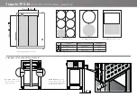
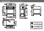
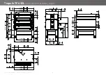
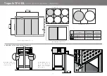
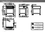
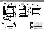
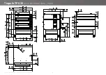
Ed. 0121 - 70702510 REV02 TIEPOLO - Pre-installation / Installation
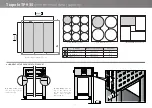
Fig. 12
N
N
L
N
AC 230
N
L
R
S
T
AC 3 230
R
S
T
IN
OUT
R
S
T
R
S
T
IN
OUT
IN
OUT
AC 3 N400
AC 3 208
L1
L2
L3
L1
L2
L3
IN
OUT
AC 3 208
L3
L2
L1
L3
L2
L1
IN
OUT
N:
R - S - T... L:
C
B
0
200
100
30
0
°C 400
600
50
0
0
20
0
100
30
0
°C 40
0
600
50
0
A
Installation
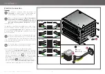
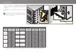
Electrical connection
Fig. 12
The electrical connection must be carried out
exclusively
by qualified personnel after reading the
safety warnings at the beginning of the manual.
Before installing the appliance,
check that systems
comply with the regulations in force
in the country
where it is going to be used and
with the specifications
indicated on the appliance rating plate
on the RH
side of the oven.
The appliance is supplied without either power cable or plug:
they must both be fitted by qualified personnel. The cable
must be only
of the type stated
and the plug fitted to it must
be suitable for the consumption and connection of the oven to
the electrical mains.
If the oven is fitted with a double chamber, there are
two power cables and two plugs. To connect the cable
to the appliance, remove the RH side panel of the oven,
let the cable through the cable gland provided and connect it
to the terminal block correctly.
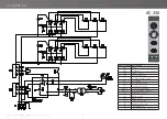
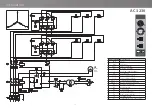
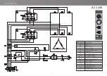
The following pages show the electrical diagrams: please
refer to the one of the specific model to connect.
For a correct electrical connection, the appliance must:
•
be included in an
equipotential system
in compliance
with the legislation in force. This connection must be made
between the various devices with the terminal marked
with the equipotential symbol
. The cable must have
a maximum cross-section of 10 mm2 (in compliance with
IEC EN 60335-2-42:2003-09) and must be yellow-green;
•
must be
grounded
to the mains (green-yellow wire);
•
must be connected to a
thermal differential switch
in
compliance with the regulations in force (0.03A A type);
earth
neutral
phases
Summary of Contents for Tiepolo PAOLO TP635L
Page 1: ...PAOLO TP635 TP635L TP935 Tiepolo OVEN Pre installation and installation manual ...
Page 34: ...34 Notes ...
Page 35: ......


