FLSUB10 and 12 Series
User’s Installation Guide
Packaging and Enclosed Parts
Please inspect your pack for any transit damage or missing parts. Notify your supplier if any discrepancies occur.
There are three (3) parts in the package: One main Speaker housing, one removable Grille and one IEC Power cord.
Only simple hand tools are required for assembly and installation.
1 Precautions and Safety Instructions
1.
Read all Instructions and retain this manual for future reference.
2.
Adhere to all Warnings, Notices, and Operating Instructions.
3.
Avoid placement near water and moisture, this could include pools, laundry, bathtubs, Kitchen sink or wet basements.
4.
Don’t not block ventilation. If placed in a cabinet or bookcase make sure there is plenty of ventilation space.
5.
Connect only to an approved Grounded 110VAC source or 230VAC. A surge protector is recommended.
6.
The FLSUB is a vinyl coated material and should only be cleaned with mild soapy water. Do Not use harsh cleaners.
7.
Warning! Do Not open the amplifier cavity. Risk of electric shock possible. There are No User Serviceable Parts on the inside.
Specifications subject to change without notice.
2 Placement
•
The optimal placement of the FLSUB subwoofer should be in the front stereo plane. By placing the FLSUB in a corner you experience a
“bass boost”
this is accomplished by sound reinforcement from adjacent walls. This translates to less required amplification and less distortion that the woofer is
trying to produce. This placement may increase standing waves depending on the room size, and make the bass sound uneven at different listening
locations.
•
It is better to install two smaller subwoofers then one bigger more expensive one. By placing two smaller subwoofers on opposite walls you can get a
more uniform axial mode cancellation.
•
Place the FLSUB in a well ventilated area to take advantage of its massive heat sink for cooling. A fan may be required if placed in a cabinet.
•
If installed in a cabinet place the front edge of the FLSUB as far forward as possible. Do Not push toward the rear of the enclosure
•
Do Not obstruct the woofer or the slotted port. This will affect the sound quality. This sub needs room to launch the bass into the room.
3 Installation
The POWER switch should be in OFF position. After checking all input/output wiring
plug the FLSUB into a grounded 110VAC Outlet.
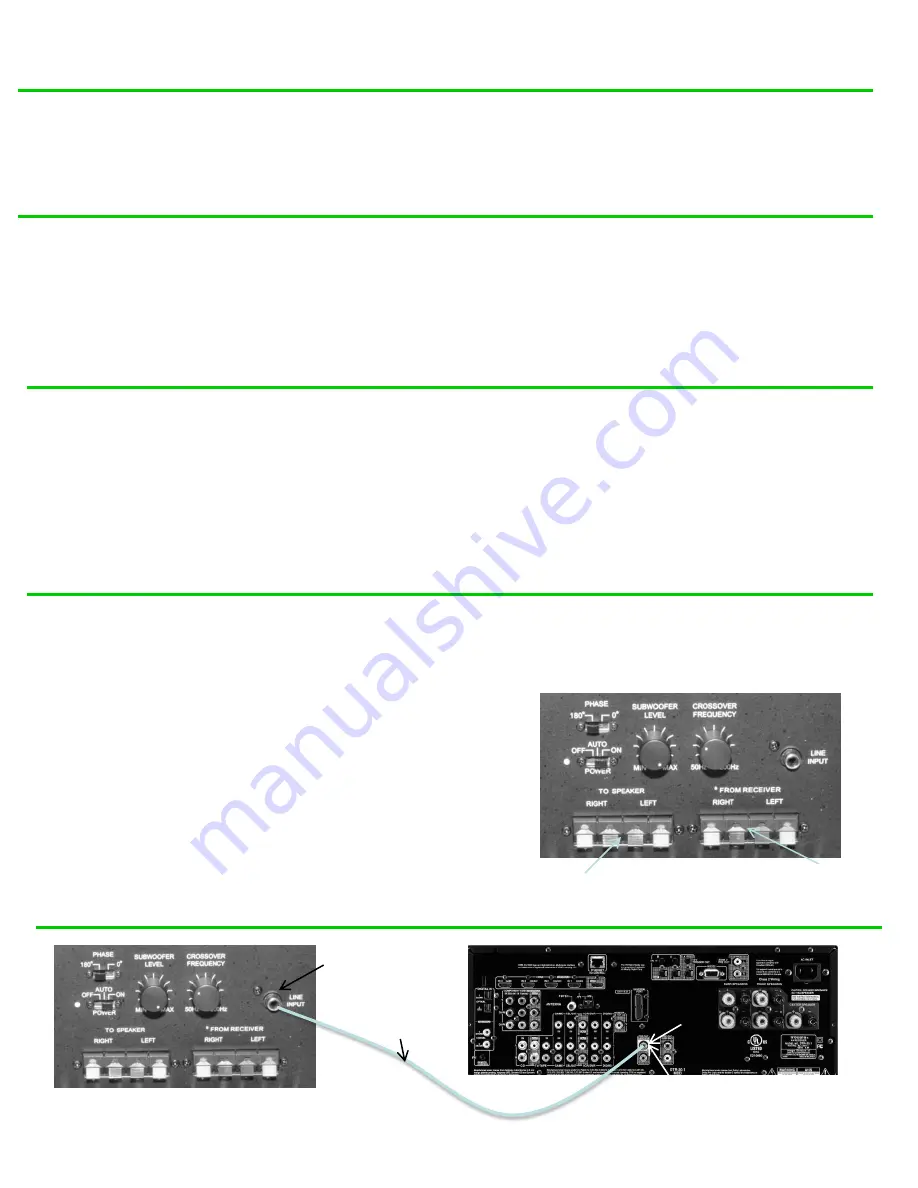
The preferred low Line Level (LFE) connection is made by connecting a quality single
RCA audio cable with male ends. If your amplifier has two outputs connect only to the
left sub out or follow amplifier directions. When using the amp LFE output turn the
FLSUB Crossover Frequency knob fully (CW) clockwise. See
Figure 1, LINE INPUT
(LFE)
and Figure 2, Hook-Up.
If you are prewiring in the wall use a 2 conductor shielded 22 gauge or larger wire to
your jack. Make sure you prewire next to a 110VAC outlet.
If your amplifier does not have a RCA SUB Output, run your Left/Right 16 gauge or
higher Speaker Output wire from the amp to the FLSUB labeled FROM RECEIVER then
from the FLSUB connect your speakers TO SPEAKER Output. See
Figure 3, SPEAKER
HOOK-UP
. With this configuration the FLSUB will extract only the Low frequencies to be
amplified by the FLSUB and pass the remainder of the frequencies to your satellite
speakers. Your satellite speakers will now work more efficiently.
WARNING! Reversing the Input and output could damage your amplifier. Verify
this connection before energizing your amplifier.
Figure 1, FLSUB Controls
Amplifier Sub Output
LINE INPUT (LFE) Connection
Sub Out
Figure 2, LINE INPUT Hook-Up
Male RCA
Cable
FLSUB RPA 020310
Low Level (LFE)
Input
Low Level
Output
Figure 1, LINE INPUT
Page 2
Speaker
Input
Speaker
Output


