CAUTION :
Never allow the flange assembly to be drawn in contact with the flange of the
*QD Bushing. There should be a gap from “1/8" TO 1/4" between them. If the
gap is closed, the shaft is seriously undersize.
Bolts of *QD Bushing:
1/4-20 x 1-1/4 , grade 5.
Bolts of Flange Assembly: 5/16-18 Socket Head Cap, equivalent to grade 8.
3.
The second *QD bushing is placed on the other shaft as described on step 1
and the second flange assembly is slipped over the bushing and assembled
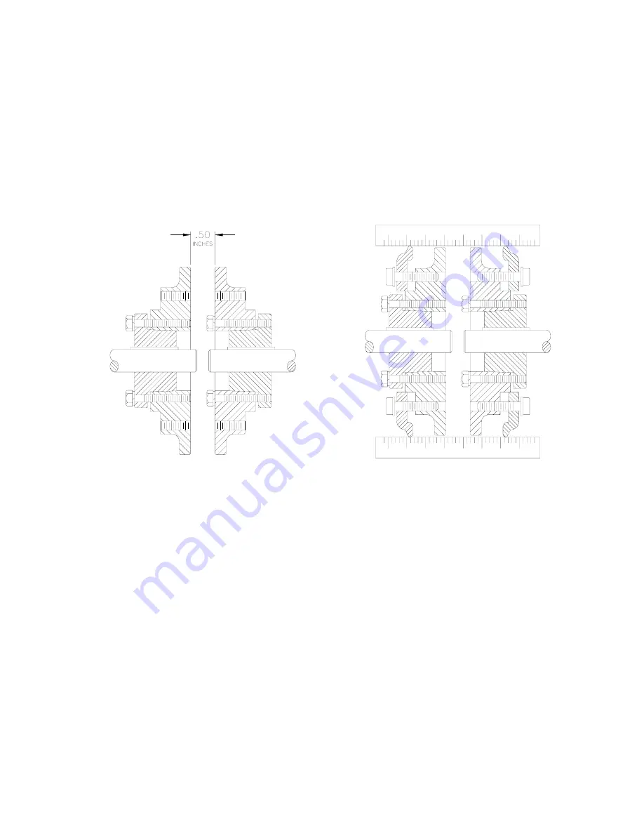
to the distance of 1-1/8" (as indicated in below/left drawing) apart following
the instructions in step 2.
FLANGE ASSEMBLY MOUNTED DISTANCE
CHECKING THE FLANGE SPACING
PRIOR TO INSTALLING FLEXIBLE ELEMENT
4.
FOR PARALLEL SHAFTS : Using a scale or straight edge, check the flange
spacing and angular misalignment at four places 90° apart around the
coupling without rotating the flanges. The flanges should be aligned so that
the dimensions at all four places do not vary more than 1/32" for best results.
Check parallel misalignment by laying the straight edge across the flange
O.D. several places around the circumference of the coupling. Parallel
misalignment not to exceed 1/32" for best results.
FOR PARALLEL AND NON PARALLEL SHAFTS : For the longest coupling
life is always best to align couplings as accurately as possible upon the initial
installation.
29


