31
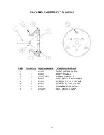
ULV NOZZLE ASSEMBLY
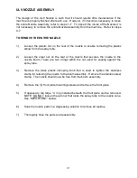
The design of the ULV Nozzle is such that it should require little maintenance if the
machine is properly flushed after each use. However, if it becomes necessary to clean
the entire Nozzle Assembly, refer to steps 1-7. To inspect the inside of the Nozzle it is
not necessary to remove the entire Nozzle Assembly from the machine. Refer to steps
4-7.
TO REMOVE THE ENTIRE NOZZLE:
1.)
Loosen the plastic nut on the rear of the nozzle to enable removing the plastic
elbow from the spray tube.
2.)
Loosen the steel nut on the rear of the nozzle that secures the nozzle to the
nozzle boom. There are two o’rings within the nut used for sealing against the
spray tube.
3.)
Remove the black plastic clamping knob that is used to tighten the stainless
clamp for retaining the nozzle to the boom assembly. Remove the stainless steel
clamp. The nozzle should now be free from the boom assembly.
4.)
Remove the (3) front plate mounting screws and remove the front plate.
5.)
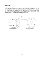
If necessary, the large “o” ring installed beneath the front plate can be removed.
NOTE: DO NOT loosen the jam nut that locks the spray tube to the nozzle cone.
See “IMPORTANT” bellow.
6.)
Soak the nozzle parts in a degreasing solution to remove all residue.
7.)
Thoroughly rinse the parts and reassembly.
Summary of Contents for MAXI-PRO 2D ULV
Page 6: ...6 MAJOR COMPONENTS DIAGRAM ...
Page 9: ...9 ...
Page 39: ...39 ...
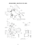
Page 43: ...43 BOOM ASSEMBLY MAXI PRO 2D P N 64905 ...
Page 50: ...50 ...

