35
Bolts of *QD Bushing: 1/4-20 x 1-1/4 , grade 5. Bolts of Flange Assembly: 5/16-18
Socket Head Cap, equivalent to grade 8.
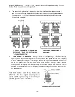
3. The second *QD bushing is placed on the other shaft as described on step 1
and the second flange assembly is slipped over the bushing and assembled to
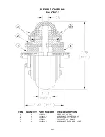
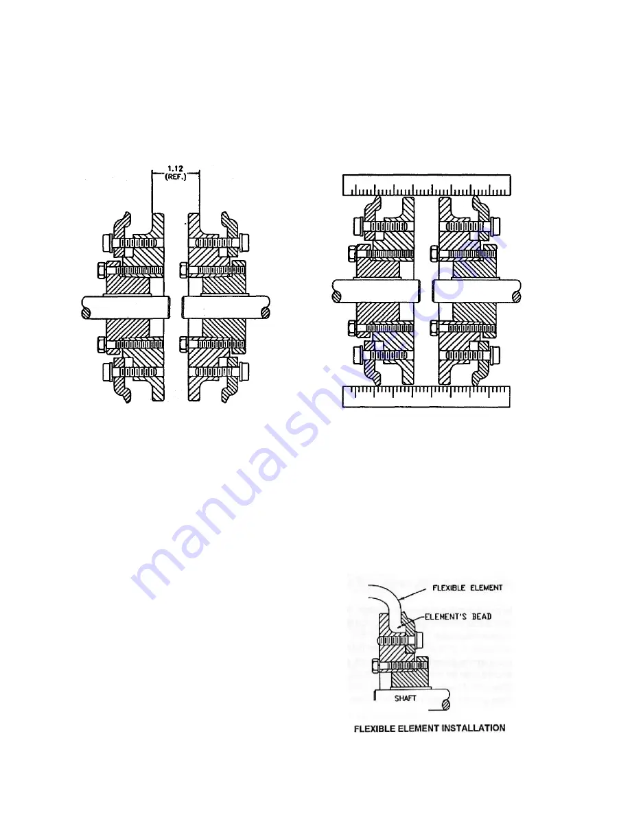
the distance of 1 -1/8" (as indicated in below/left drawing) apart following the
instructions in step 2.
4.
FOR PARALLEL SHAFTS
: Using a scale or straight edge, check the flange
spacing and angular misalignment at four places 90° apart around the coupling
without rotating the flanges. The flanges should be aligned so that the dimensions
at all four places do not vary more than 1/32" for best results. Check parallel
misalignment by laying the straight edge across the flange O.D. several places
around the circumference of the coupling. Parallel misalignment not to exceed 1/32"
for best results.
FOR PARALLEL AND NON PARALLEL
SHAFTS : For the longest coupling life is
always best to align couplings as accurately as
possible upon the initial installation.
FLANGE ASSEMBLY MOUNTED
DISTANCE PRIOR TO INSTALLING
FLEXIBLE ELEMENT
CHECKING THE FLANGE
SPACING
Summary of Contents for MAXI-PRO 2D ULV
Page 6: ...6 MAJOR COMPONENTS DIAGRAM ...
Page 9: ...9 ...
Page 39: ...39 ...
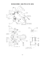
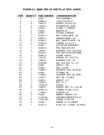
Page 43: ...43 BOOM ASSEMBLY MAXI PRO 2D P N 64905 ...
Page 50: ...50 ...

