background image

Curtis Front End Loader Blade (F.E.L.B.) Assembly Instructions (continued)


7.) 

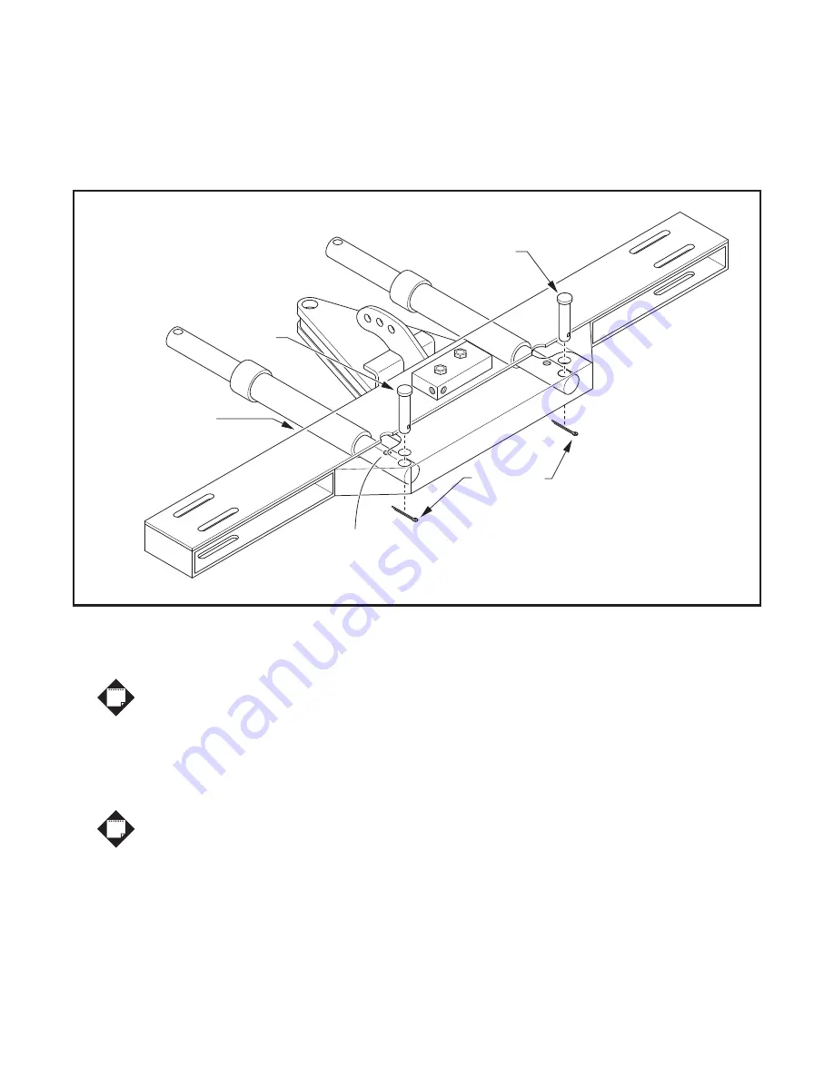
Locate both 10" Angle Cylinders (1TBP27) and mount one to each side of the A-Frame. The Angle Cylinders 


     will be inserted into the A-Frame at the front through the slots, with the Hydraulic Port facing up and visible 


     through the opening at the top of the A-Frame. Mount each Angle Cylinder to the A-Frame with a 1" x 3" Clevis 


     Pin (1TBP73) and secure each Clevis Pin with a 3/16" x 1-1/2" Cotter Pin (1TBP24). Refer to Figure 8.


8.)

 Lift the A-Frame above the Trip Frame, and insert the A-frame and Angle Cylinders into the Trip Frame.


     Apply grease to the 1"-8 x 6" Gr.5 Center Bolt (1TBP25) and insert through the Trip Frame and A-Frame.


     Secure the Center Bolt with a 1" Nylon Lock Nut (1TBP26). Refer to Figure 9.


Do not over tighten the Nylon Lock Nut, the A-Frame must pivot freely.


9.)

 Swing A-Frame to Left or Right and align hole in Angle Cylinder Ram with the corresponding hole in Trip 


      Frame. Install (1) 1" x 4" Clevis Pin (1TBP23) through Trip Frame and Angle Cylinder Ram.


      Secure Clevis Pin with (1) 3/16" x 1-1/2" Cotter Pin (1TBP24). Swing A-Frame to opposite side and


      repeat alignment and pinning procedure. Swing A-Frame back to the center.


It may be necessary to extend the Angle Cylinder Piston Rod 1-2" to make


the connection to the Trip Frame. To do this, insert a long pin or ratchet handle


through the Piston Rod and work the piston Rod side to side while pushing downward.


10.) 

Return the A-Frame to the center position after the Angle Cylinders are secured to the Moldboard.


       Using the A-Frame as a lever, grasp the A-Frame by the cross-brace and pull back, raising the Moldboard


       to a vertical position.

Figure 8. Mount Angle Cylinders to A-Frame

1" x 3"

Clevis Pin

1" x 3"

Clevis Pin

Angle Cylinders are

inserted into slots in

the front of A-Frame

3/16" x 1-1/2"

Cotter Pins

install from

below

Hose Ports up

NOTE

NOTE

7 of 14

Summary of Contents for Sno-Pro 5FBMQA

Page 1: ...al and on the Loader Blade WARNING ALWAYS travel at reduced speed when Loader Blade is attached ALWAYS ensure Lift Chain if used is securely attached to Grab Hook ALWAYS familiarize yourself with area...

Page 2: ...d Loader Blade Illustrated Parts List T r a c t o r A r m s T r a c t o r A r m s 1 7 8 3 Bypass Relief Valve See Detail 22 6 2 4 20 4 18 18 19 23 26 25 25 16 15 5 9 12 11 10 13 14 21 17 24 28 DETAIL...

Page 3: ...ng Edge 8 Cutting Edge 4 2 2 4 4 4 4 4 1 1 1 Trip Springs L Moldboard Spring Mount Bracket R Moldboard Spring Mount Bracket Spring Eyebolt 5 8 11 Nylon Locknut 5 8 11 Jam Nut 1 x 4 Clevis Pin 3 16 x 1...

Page 4: ...Refer to Figure 6 The Upper Spring mounting holes will give a lighter trip when encountering an obstacle The Lower Spring mounting holes will give a heavier trip when encountering an obstacle 4a Thre...

Page 5: ...nsion is achieved A B Install End Caps End Cap Install Clevis Pin and secure with Cotter Pin Note orientation of Left and Right Clevis Pins Trip Frame is attached to Moldboard with 4 Clevis Pins in lo...

Page 6: ...se Lower four Holes for heavier Plow trip when striking an obstacle Use Upper four Holes for lighter Plow trip when striking an obstacle Trip Frame Spring Mounting Tabs on Trip Frame TRIP FRAME FRONT...

Page 7: ...9 Swing A Frame to Left or Right and align hole in Angle Cylinder Ram with the corresponding hole in Trip Frame Install 1 1 x 4 Clevis Pin 1TBP23 through Trip Frame and Angle Cylinder Ram Secure Clevi...

Page 8: ...ariations in tractor hydraulic systems and fittings two hoses with 1 4 male NPT threads have been provided to connect between the tractor and By Pass Valve but fittings and quick connectors have not M...

Page 9: ...Figure 10 Install Hydraulic Hoses Figure 11 F E L B with Skidsteer Reference View Connect Hydraulic Hoses from L R Angle Cylinders to By Pass Relief Valve R e l i e f V a l v e 9 of 14...

Page 10: ...Cross Brace using the holes in the Loader Brackets as guides Bolt inboard Brackets to A Frame Rear Cross Brace with 1 2 x 1 3 4 Bolts in the top of the A Frame 2 per Bracket and 1 1 2 length Bolts in...

Page 11: ...1 Find a secure spot on the Loader Cross Brace to wrap Lift Chain 1TBP31 around The Chain should go over the Top of the Cross Brace and wrap underneath Refer to Figure 13 above Be certain Chain will n...

Page 12: ...12 of 14 Figure 15 John Deere Quick Attach Adaptor Part Number 5FBMQA Figure 14 Skid Steer Adaptor Part Number 1FELB1BW...

Page 13: ...existing Tractor Loader Valve 5 Route two additional Dealer Supplied Hoses from Ports marked A and B on existing Tractor Loader Valve down along Tractor Loader Arms to corresponding A and B ports on C...

Page 14: ...cility or refund that portion of the purchase price allocatable to the defective Product The remedy contained in the preceding sentence will be the sole and exclusive remedy against Curtis EXCEPT AS S...

Reviews:

Related manuals for Sno-Pro 5FBMQA