background image

8 of 14

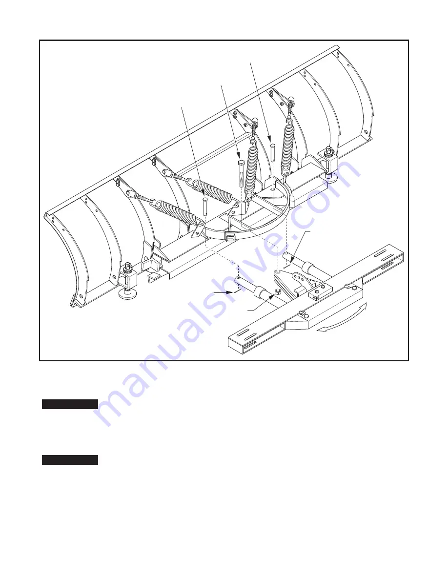
Figure 9. Mount A-Frame to Trip Frame

1" Nylon

Lock Nut

1" x 6" Bolt

Apply Grease

3/16" x 1-1/2"

Cotter Pin

3/16" x 1-1/2"

Cotter Pin

1" x 4" Clevis Pin


 S

w

in

g


A-F

ram

L&

R


t

o

 ins

e

r

t Pi

n

s

1" x 4" Clevis Pin


11.)

 Locate and install the two Hydraulic Hoses (1TBP72) to each side of the By-Pass Relief Valve and to the


       corresponding Ports on the Left and Right Angle Cylinders.


Do not

 use Teflon Tape on the Hydraulic Fittings as it may contaminate the Hydraulic


System causing a malfunction. Use a high quality paste type thread sealant on all N.P.T. 


fittings.


Due to the large number of variations in tractor hydraulic systems and fittings, two hoses


with 1/4" male NPT threads have been provided to connect between the tractor and


By-Pass Valve, but fittings and quick connectors have not.  Most skid steer loaders 


have extra lines which can be tied into. Some tractors have an auxillary valve that can be 


used, or an optional valve kit can be purchased from Curtis. The last option is to connect 


the lines from the loader tilt cylinders and tie them into the bypass block. Be sure to


connect before the T-Fitting that connects the left and right tilt cylinders. If using this


option the loader blade will need to be supported with Lift Chain provided. See Step 12 


below.


12.)

 Attach Lift Chain (1TBP30A) to A-Frame assembly with 5/16" Anchor Shackle (1TBP31).

IMPORTANT

IMPORTANT

Summary of Contents for Sno-Pro 5FBMQA

Page 1: ...al and on the Loader Blade WARNING ALWAYS travel at reduced speed when Loader Blade is attached ALWAYS ensure Lift Chain if used is securely attached to Grab Hook ALWAYS familiarize yourself with area...

Page 2: ...d Loader Blade Illustrated Parts List T r a c t o r A r m s T r a c t o r A r m s 1 7 8 3 Bypass Relief Valve See Detail 22 6 2 4 20 4 18 18 19 23 26 25 25 16 15 5 9 12 11 10 13 14 21 17 24 28 DETAIL...

Page 3: ...ng Edge 8 Cutting Edge 4 2 2 4 4 4 4 4 1 1 1 Trip Springs L Moldboard Spring Mount Bracket R Moldboard Spring Mount Bracket Spring Eyebolt 5 8 11 Nylon Locknut 5 8 11 Jam Nut 1 x 4 Clevis Pin 3 16 x 1...

Page 4: ...Refer to Figure 6 The Upper Spring mounting holes will give a lighter trip when encountering an obstacle The Lower Spring mounting holes will give a heavier trip when encountering an obstacle 4a Thre...

Page 5: ...nsion is achieved A B Install End Caps End Cap Install Clevis Pin and secure with Cotter Pin Note orientation of Left and Right Clevis Pins Trip Frame is attached to Moldboard with 4 Clevis Pins in lo...

Page 6: ...se Lower four Holes for heavier Plow trip when striking an obstacle Use Upper four Holes for lighter Plow trip when striking an obstacle Trip Frame Spring Mounting Tabs on Trip Frame TRIP FRAME FRONT...

Page 7: ...9 Swing A Frame to Left or Right and align hole in Angle Cylinder Ram with the corresponding hole in Trip Frame Install 1 1 x 4 Clevis Pin 1TBP23 through Trip Frame and Angle Cylinder Ram Secure Clevi...

Page 8: ...ariations in tractor hydraulic systems and fittings two hoses with 1 4 male NPT threads have been provided to connect between the tractor and By Pass Valve but fittings and quick connectors have not M...

Page 9: ...Figure 10 Install Hydraulic Hoses Figure 11 F E L B with Skidsteer Reference View Connect Hydraulic Hoses from L R Angle Cylinders to By Pass Relief Valve R e l i e f V a l v e 9 of 14...

Page 10: ...Cross Brace using the holes in the Loader Brackets as guides Bolt inboard Brackets to A Frame Rear Cross Brace with 1 2 x 1 3 4 Bolts in the top of the A Frame 2 per Bracket and 1 1 2 length Bolts in...

Page 11: ...1 Find a secure spot on the Loader Cross Brace to wrap Lift Chain 1TBP31 around The Chain should go over the Top of the Cross Brace and wrap underneath Refer to Figure 13 above Be certain Chain will n...

Page 12: ...12 of 14 Figure 15 John Deere Quick Attach Adaptor Part Number 5FBMQA Figure 14 Skid Steer Adaptor Part Number 1FELB1BW...

Page 13: ...existing Tractor Loader Valve 5 Route two additional Dealer Supplied Hoses from Ports marked A and B on existing Tractor Loader Valve down along Tractor Loader Arms to corresponding A and B ports on C...

Page 14: ...cility or refund that portion of the purchase price allocatable to the defective Product The remedy contained in the preceding sentence will be the sole and exclusive remedy against Curtis EXCEPT AS S...

Reviews:

Related manuals for Sno-Pro 5FBMQA