DuraCOR 312
Chapter 4 - Operational Description
Page 26 of 59
MNL-0670-01 Rev A2
ECO-5931
Effective: 03 Jun 20
ARINC 429
CAN Bus
Frame grabbers (video capture)
GPS
Wi-Fi
Serial ports
Analog/digital data acquisition cards
GPIO
SATA
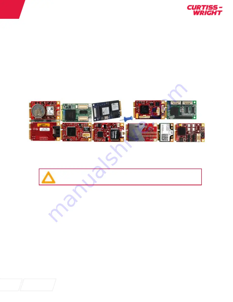
Figure 8: Mini-PCIe Cards from various Manufactureres
Installing Mini-PCIe Cards into the DuraCOR 311 Mission Computer
Caution! ESD Sensitive Components
Follow standard ESD and FOD controls to avoid damage to the internal components.
1. Remove the 15x 2-56 bolts using a #1 Philips screwdriver and remove base.
2. Insert a mini-PCIe card into slot 1 or 2. Use 2x 2mm screw with thread-locker, such as Loctite
222, to secure card to motherboard.
3. Connect the corresponding cable from the mini-PCIe card to the expansion pins of the DuraCOR
312 J4 connector as required
a. A custom cable is required. See Integrating mini-PCIe Cards and Chapter 3 for available
I/O options.
4. Close the unit and tighten screws to 34.4 in. oz. [0.24 Nm]. Use a thread-locker, such as Loctite
222.
Integrating Mini-PCIe Cards
To create a cable to bring out the I/O from the mini-PCIe cards through the circular connector (J4) use the
information in Chapter 3 for the available I/O. Special care may be required for certain high speed
protocols. Refer to protocol standards for guidance.
Most configurable IO pins do not contain any
ESD protection unless provided by the add-on card or custom cable.


