Curtiss-Wright | PG Drives Technology
SK77981-14
131 | R-net Technical Manual | Chapter 4 – ELPM 90, JSM-LED &
SM
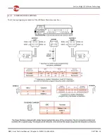
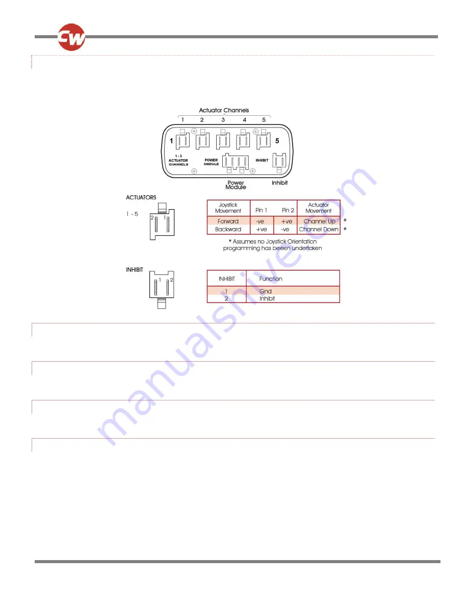
6.1.2 SEATING MODULE WIRING
The following diagram gives details of the Seating Module connections.
6.1.3 CRIMPING
Refer to Chapter 2- Installation.
6.2
WIRE GAUGE AND TYPES
Refer to Chapter 2- Installation.
6.3
BATTERY AND MOTOR CONNECTIONS
Refer to Chapter 2- Installation.
6.4
EL PM TO SEATING MODULE CONNECTIONS
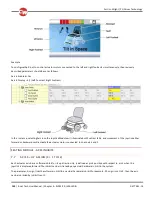
Use only a Curtiss-Wright supplied Seating Module Cable to connect between the EL PM and the Seating Module. The 4-way
connector on this cable carries Actuator and Inhibit 2 connections, while the two 2 -way connectors on the other end should be
connected to the EL PM’s Actuator and Inhibit 2 connections.
NOTE:
If it is required to connect a switch directly to the Inhibit 2 connector on the EL PM, then the 2 -way connector for Inhibit 2 on
the Seating Module Cable should not be connected.


