Curtiss-Wright | PG Drives Technology
SK77981-14
138 | R-net Technical Manual | Chapter 5 – Encoder Module
3
MOUNTING
3.1
ORIENTATION
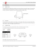
The Encoder Module should be mounted so that water cannot enter and remain in the connector recesses. The recommended
mounting orientation is such that the Module is lying flat. The function of the Encoder Module is not sensitive to mounting
orientation. The electronics compartment of the controller has an IPX4 dust and water rating.
3.2
POSITION
The Encoder Module must be mounted in a position where it is not exposed to levels of water, dust, shock or vibration above
those expected on a mobility application. The Encoder Module has been tested in accordance with IS07176/14 with respect to
these conditions. Contact Curtiss-Wright if you need further advice.
3.3
CONNECTIONS
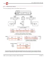
There are two 4-way connectors, one for each encoder. The pin-out for these connectors is as below.
Encoder Module connector kit is D51261 or the parts can be sourced directly from Molex
Housing-
43025-0400
Crimp-
43030-0007
M2 Pin
Function
24V
1
Encoder Ground 2
Encoder A
3
Encoder B
4
M1 and M2 pin-out are viewing rear of mating connector.
For Encoder A and Encoder B signal details, refer to the sections Invert M1 and Invert M2.


