background image

921

200921

TUNING

4

STRAP

941

360941

FLAT

#8

4

WASHER

EC

ALUMINUM

1/2" x 38"

1

TUBE

(1.3 x 96.5 cm)

ED

ALUMINUM

1/2" x 12-7/16"

1

TUBE

(1.3 x 31.6 cm)

RM1

REDDI-MATCH

5-1/2"

1

(2 Meter)

(14.0 cm))

RM2

REDDI-MATCH

3-3/8"

1

(70 cm)

(8.6 cm)

3

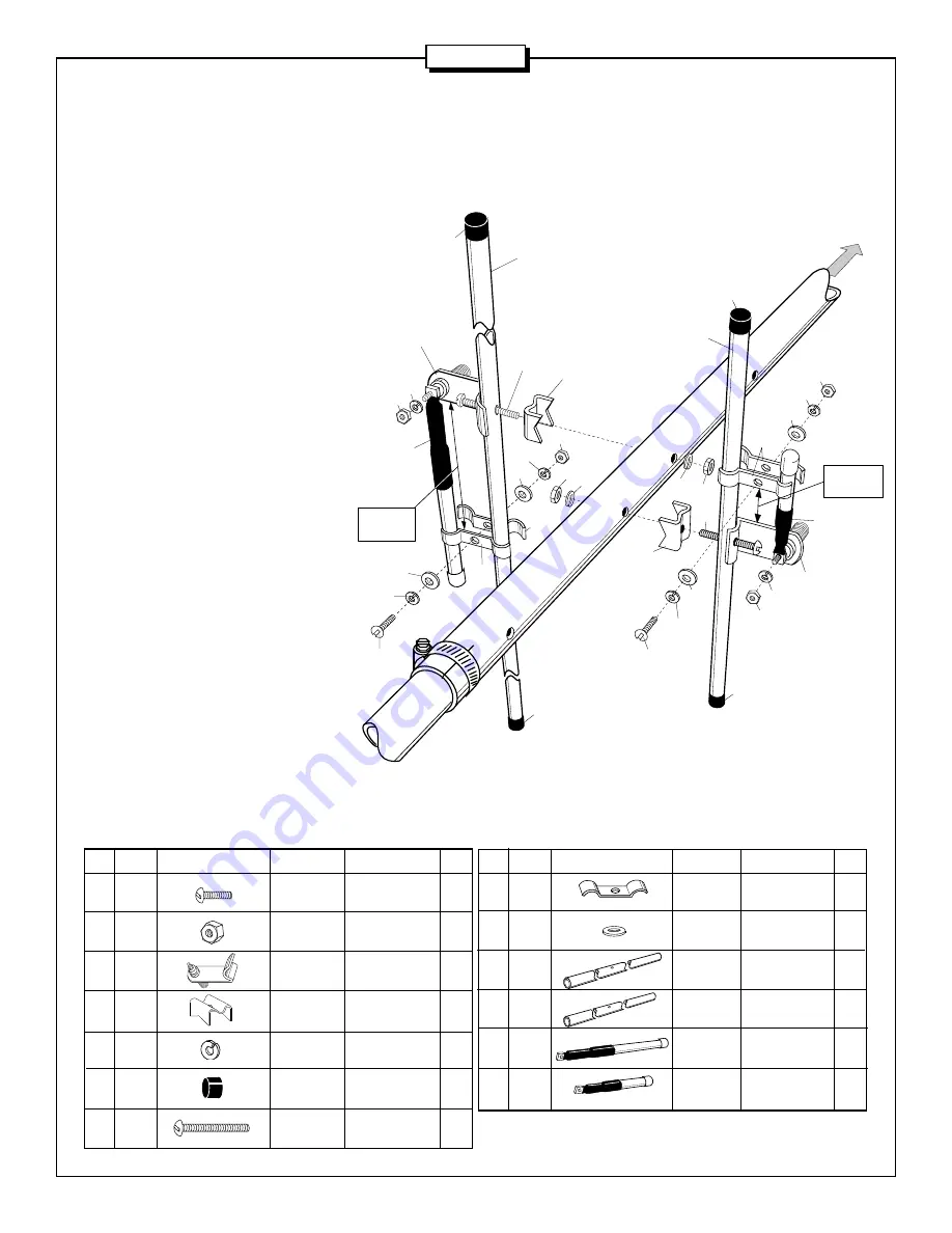
#2 - REDDI-MATCH ASSEMBLY

FIGURE B

Assemble the driven element tubes (EC &
ED) and connector brackets (23) to the
boom at the positions shown in figure D
using the hardware shown in figure B.  Note
that both connectors point towards the back
of the boom.  Attach the Reddi-Match sub-
assemblies starting with element EC.
Loosely attach the Reddi-Match straps
(921) to the driven element (EC) as shown.
Slide the longer Reddi-Match sub-assem-
bly (RM1) through the Reddi-Match straps
and secure to the connector using washer
(41)  and nut (11).  Set the distance between
the connector bracket (23) and the straps
(921) as shown in figure B and tighten the
hardware.  Attach the other Reddi Match
sub-assembly (RM2) to the other driven
element (ED) using washer (41) and nut
(11).  Be sure to set the Reddi-Match strap
dimension shown in figure B.  Install end
caps (53) on ends of elements EC and ED.

A270-10S

9

010009

SS MACHINE

8-32 x 5/8"

2

SCREW

(1.6 cm)

11

010011

SS

8-32

6

HEX NUT

23

190023

CONNECTOR

2

BRACKET

26

190026

ALUMINUM

7/8"

2

BRACKET

(2.2 cm)

41

011941

SS LOCK

#8

8

WASHER

53

050053

PLASTIC

1/2"

4

CAP

 (1.3 cm)

120

010120

SS MACHINE

8-32 x 2"

2

SCREW

(5.1 cm)

KEY        P/N                     DISPLAY                         DESC                         SIZE                  QTY

KEY        P/N                     DISPLAY                         DESC                         SIZE                  QTY

3-1/16"

(7.78 cm)

2m

70 cm

Back

53

EC

26

120

23

41

11

941

41

11

41

11

921

921

941

41

9

RM1

26

941

41

9

41

11

23

941

41

11

11

41

921

120

53

53

53

RM2

1-1/8"

(2.86 cm)

ED

Summary of Contents for A270-10S

Page 1: ...951377 1 94 C O R P O R A T I O N ASSEMBLY AND INSTALLATION A270 10S 2 METER 70 CM YAGI ANTENNA 144 148 430 450 MHz ...

Page 2: ...ization normally SSB and CW mount the A270 10S with the elements parallel to the ground SYSTEM GROUNDING Direct grounding of the antenna mast and tower is very important This serves as protection from lightning strikes static buildup and high voltage which is present in the radio equipment connected to the antenna A good electrical connection should be made to one or more ground rods or other exte...

Page 3: ...aluminum flat washer 4 BA 1 x 32 2 5 x 81 3 cm aluminum tubing slotted one end 1 BB 7 8 x 48 2 2 x 122 cm aluminum tubing 1 EA 40 3 4 103 5 cm element rod 1 EB 14 15 16 37 9 cm element rod 1 EC 1 2 x 37 1 4 1 3 x 94 6 cm element tube drilled in ctr 1 ED 1 2 x 12 7 16 1 3 x 31 6 cm element tube drilled in ctr 1 EE 12 7 16 31 6 cm element rod 1 EF 12 3 16 30 9 cm element rod 1 EG 12 1 16 30 6 cm ele...

Page 4: ...aps and secure to the connector using washer 41 and nut 11 Set the distance between the connector bracket 23 and the straps 921 as shown in figure B and tighten the hardware Attach the other Reddi Match sub assembly RM2 to the other driven element ED using washer 41 and nut 11 Be sure to set the Reddi Match strap dimension shown in figure B Install end caps 53 on ends of elements EC and ED A270 10...

Page 5: ...re on opposite sides of the boom ELEMENT LENGTH KEY NO INCHES CM EA 1 40 3 4 103 5 EB 2 14 15 16 37 9 EC 3 37 1 4 94 6 ED 4 12 7 16 31 6 EE 5 12 7 16 31 6 EF 6 12 3 16 30 9 EG 7 12 1 16 30 6 EH 8 36 3 8 92 4 EI 9 35 13 16 91 0 EJ 10 34 13 16 88 4 TABLE A ELEMENTS EA EB EC ED EE EF EG EH EI EJ 11 3 4 29 84 cm 3 3 4 9 5 cm 1 13 16 4 6 cm 4 3 16 10 6 cm 5 1 4 13 3 cm 6 13 16 17 3 cm 2 5 16 5 9 cm 14 ...

Page 6: ...arly visible 5 MAST MOUNT 4 FEEDLINE HARNESS Slide back all four vinyl boots on the feedline harness FL to expose the male PL 259 coaxial connectors Unthread both connectors from the coaxial T connector Apply silicone grease 116 to the outer threads of the in line connectors on the T connector and re attach both coaxial male connectors to the T connector Apply silicone grease to the outer shells o...

Page 7: ... Wind Load ft2 m2 725 07 Weight lb kg 1 8 81 Hardware Stainless steel TAPE TAPE FL TAPE 115 Your PL 259 connector FL cushcraft SILICONE GREASE cushcraft Do NOT coat center pin or socket Your feedline cushcraft 6 FEEDLINE Tape your feedline down the mast figure G Any length of feedline can be used with your A270 10S The shortest length cable will have the least loss Before installing your connector...

Page 8: ...ts authorized representatives This warranty is in lieu of all other expressed warranties any implied warranty is limited in duration to one year Cushcraft Corporation shall not be liable for any incidental or consequential damages which may result from a defect Some states do not allow limitations on how long an implied warranty lasts or exclusions or limitations of incidental or consequential dam...

Reviews: