background image

A50-3S

5

KEY      P/N                 DISPLAY                     DESC                     SIZE             QTY

KEY      P/N                 DISPLAY                     DESC                     SIZE             QTY

402 010402

U-BOLT

1-1/2"

1

(3.8 cm)

CB

CONNECTOR

1

BRACKET

RM

REDDI MATCH

17"

1

ASSEMBLY

(41.2 cm)

9

010009

SS MACHINE

8-32 X 5/8"

2

SCREW

(1.59 cm)

941 011941

SS LOCK

#8

3

WASHER

11

010011

SS HEX

8-32

3

NUT

32

190032

U-BOLT

1-1/2"

1

BRACKET

(3.8 cm)

69

200069

TUNING

1

STRAP

84

010084

SS LOCK

1/4"

2

WASHER

(.63 cm)

85

010085

SS HEX

1/4"

2

NUT

(.63 cm)

FIGURE E

70

190070

MAST MT.

4" X 6"

1

PLATE

(10.16 x 15.2 cm)

118 010118

HEX

5/16"

8

NUT

(.8 cm)

119 010119

LOCK

5/16"

8

WASHER

(.8 cm)

326 290326

DANGER

1

LABEL

403 010403

U-BOLT

1-5/8"

2

(4.13 cm)

404 010404

U-BOLT

2-1/8"

2

(5.4 cm)

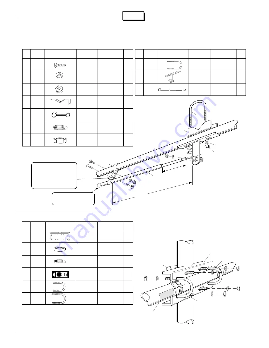
#4 - BOOM TO MAST ASSEMBLY

Assemble and mount the mast bracket to the boom centered over the
AA tube.  Refer to figure E for assembly.

KEY      P/N                 DISPLAY                     DESC                     SIZE              QTY

FIGURE D

MAST

118

119

118

119

118

119

404

403

403

70

326

AA

After the Reddi-Match tube has 
been attached to the driven 
element, adjust the angle of the 
tuning strap (69) to a point 
which brings the Reddi-Match 
tube into parallel with the driven 
element. 

69

9

11

941

11

CB

EA

32

405

RM

84

85

X

SET

941

NOTE: For vertical polarization 
the Reddi-Match assembly 
should point skyward.

#3 - REDDI MATCH ASSEMBLY

Slide the Reddi Match tube (RM) through the tuning strap (69).  Connect the flattened rod to the screw on the connector (figure D).  Slide the poly
tube over the rod up to the flattened end.  Adjust to the dimensions shown in Table 1 for horizontal polarization or Table 2  for vertical polarization.
Tighten all connections.

Summary of Contents for A50-3S

Page 1: ...951364 12 94 A50 3S 3 ELEMENT 6 METER BEAM COMMUNICATIONS ANTENNAS ASSEMBLY AND INSTALLATION ...

Page 2: ...d be made to one or more ground rods or other extensive ground system directly at the base of the tower or mast using at least 10AWG ground wire and non corrosive hardware For details and safety standards consult the National Electrical Code You should also use a coaxial lightning arrester Cushcraft offers several different models such as LAC 1 LAC 2 and the LAC 4 series ASSEMBLY Assemble your ant...

Page 3: ...p 1 70 190070 4 x 6 10 2 x 15 2 cm formed mast plate 1 84 010084 1 4 63 cm stainless steel lock washer 6 85 010085 1 4 63 cm stainless steel hex nut 6 115 050115 Connector boot 1 116 240116 Silicone package 1 118 010118 5 16 8 cm stainless steel hex nut 8 119 010119 5 16 8 cm stainless steel lock washers 8 326 290326 Danger label 1 402 010402 1 1 2 3 8 cm stainless steel U bolt 3 403 010403 1 5 8 ...

Page 4: ... the threads socket pointing to the mast mount Adjust the antenna to your preferred portion of the 6 meter band using Table 1 if you ve chosen horizontal polarization or Table 2 for vertical polarization Tighten all connections Horizontal Polarization 50 MHz 51 MHz 52 MHz 53 MHz 54 MHz REF in 34 1 2 34 1 2 32 1 2 32 1 2 30 1 2 cm 87 63 87 63 82 55 82 55 77 5 DE in 31 1 4 30 1 4 29 1 4 28 1 4 27 1 ...

Page 5: ... 1 6 x 95 2 cm EC ALUM 5 8 x 34 1 4 2 TUBING 1 6 x 87 0 cm ED ALUM 5 8 x 31 1 2 2 TUBING 1 6 x 80 0cm 27 050027 PLASTIC 5 8 6 CAP 1 6 cm 32 190032 U BOLT 1 1 2 3 BRACKET 3 8 cm 33 190033 BACKING 1 1 2 2 PLATE 3 8 cm 69 200069 TUNING 1 STRAP 84 010084 LOCK 1 4 4 WASHER 63 cm 85 010085 HEX 1 4 4 NUT 63 cm 402 010402 U BOLT 1 1 2 2 3 8 cm 409 030409 SS WORM 3 4 6 CLAMP 1 9 cm KEY P N DISPLAY DESC SIZ...

Page 6: ... Assemble and mount the mast bracket to the boom centered over the AA tube Refer to figure E for assembly KEY P N DISPLAY DESC SIZE QTY FIGURE D MAST 118 119 118 119 118 119 404 403 403 70 326 AA After the Reddi Match tube has been attached to the driven element adjust the angle of the tuning strap 69 to a point which brings the Reddi Match tube into parallel with the driven element 69 9 11 941 11...

Page 7: ... 8 m 117 in 300 cm 6 ft 1 8 m 1 5 2 in 3 8 5 1cm 1 80 ft2 0 17 m2 7 lb 3 2 kg 48 PERIMETER ROAD MANCHESTER NH 03108 603 627 7877 FAX 603 627 1764 COMMUNICATIONS ANTENNAS SPECIFICATIONS SUBJECT TO CHANGE WITHOUT NOTICE LIMITED WARRANTY Cushcraft Corporation P O Box 4680 Manchester New Hampshire 03108 warrants to the original consumer purchaser for one year from date of purchase that each Cushcraft ...

Reviews: