background image

A627013S

70 cm

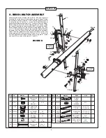
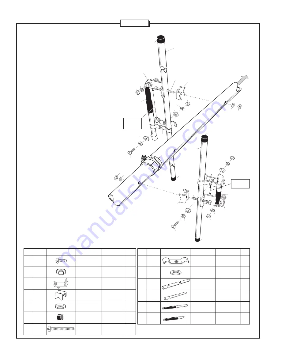
2. REDDI-MATCH ASSEMBLY

Assemble the driven element tubes (EC & ED) and connector
brackets (23) to the boom at the positions shown in figure D using
the hardware shown in figure B.  Note that both connectors point
towards the back of the boom.  Attach the Reddi-Match sub-
assemblies starting with element EC.  Loosely attach the Reddi-
Match straps (921) to the driven element (EC) as shown.  Slide
the longer Reddi-Match sub-assembly (RM1) through the Reddi-
Match straps and secure to the connector using washer (41)  and
nut (11).  Set the distance between the connector bracket (23) and
the straps (921) as shown in figure B and tighten the hardware.
Attach the other Reddi Match sub-assembly (RM2) to the other
driven element (ED) using washer (41) and nut (11).  Be sure to
set the Reddi-Match strap dimension shown in figure B.  Install
end caps (53) on ends of elements EC and ED.

79

010079

SS MACHINE

8-32 x 5/8"

2

SCREW

(1.6 cm)

11

010011

SS

8-32

6

HEX NUT

23

23CB

CONNECTOR

2

BRACKET

26

190026

ALUMINUM

7/8"

2

BRACKET

(2.2 cm)

41

011941

SS LOCK

#8

8

WASHER

53

050053

PLASTIC

1/2"

4

CAP

 (1.3 cm)

120

010120

SS MACHINE

8-32 x 2"

2

SCREW

(5.1 cm)

921

200921

TUNING

4

STRAP

941

360941

FLAT

#10

4

WASHER

EC

A270-

ALUMINUM

1/2" x 37-1/4"

1

10SEC

TUBE

(1.3 x 96.5 cm)

ED

A270-

ALUMINUM

1/2" x 12-7/16"

1

10SED

TUBE

(1.3 x 31.6 cm)

RM1

A270-

 REDDI-MATCH

5-1/2"

1

10SRM1

(2 Meter)

(14.0 cm))

RM2

A270-

REDDI-MATCH

3-3/8"

1

10SRM2

(70 cm)

(8.6 cm)

3-1/16"

(7.78 cm)

2m

53

EC

26

120

23

41

11

941

41

11

921

921

941

41

79

RM1

53

11

41

Back

26

941

41

79

41

11

23

941

41

11

921

120

53

53

RM2

1-1/8"

(2.86 cm)

ED

KEY

P/N

DISPLAY

DESC

SIZE

QTY

41

11

FIGURE B

KEY

P/N

DISPLAY

DESC

SIZE

QTY

4

Summary of Contents for A627013S

Page 1: ...A627013S 6 METER 2 METER 70 CM TRIBAND ANTENNA 144 148 430 450 MHz 951488 10 99 ASSEMBLY AND INSTALLATION INSTRUCTIONS ...

Page 2: ...tenna mast and tower is very important This serves as protection from lightning strikes static buildup and high voltage which is present in the radio equipment connected to the antenna A good electrical connection should be made to one or more ground rods or other extensive ground system directly at the base of the tower or mast using at least 10AWG ground wire and non corrosive hardware For detai...

Page 3: ...010120 8 32 x 2 5 1 cm stainless steel machine screw 2 231 010231 8 32 x 1 3 4 4 4 cm stainless steel machine screw 8 326 290326 Danger label 1 401 010401 3 x 1 3 4 7 6 x 4 4 cm stainless steel U bolt 2 402 010402 1 4Ó 20 x 1 3 4Ó stainless steel U bolt 3 404 010404 3 1 4 x 2 7 16 8 3 x 6 2 cm stainless steel U bolt 2 409 030409 3 8 7 8Ó 95 2 2 cm stainless steel worm clamp 6 410 030410 7 16 1Ó 1 ...

Page 4: ... cm 410 030410 WORM 7 16Ó 1 1 CLAMP 1 1 2 5 cm 412 030412 WORM 11 16Ó 1 1 2 1 CLAMP 1 7 3 8 cm KEY P N DISPLAY DESC SIZE QTY KEY P N DISPLAY DESC SIZE QTY FIGURE A 3 MASTER PARTS LIST continued KEY PART DESCRIPTION QUANTITY 103 1 2 262 8 cm 412 410 BB BA BC 36 91 44 cm 32 81 28 cm 48 121 92 cm EJ A27010SEJ 34 13 16 88 4 cm element rod 1 CB A50CB Connector Bracket Assembly 1 6MEA A50EA 3 4Ó x 48 1 ...

Page 5: ...lement ED using washer 41 and nut 11 Be sure to set the Reddi Match strap dimension shown in figure B Install end caps 53 on ends of elements EC and ED 79 010079 SS MACHINE 8 32 x 5 8 2 SCREW 1 6 cm 11 010011 SS 8 32 6 HEX NUT 23 23CB CONNECTOR 2 BRACKET 26 190026 ALUMINUM 7 8 2 BRACKET 2 2 cm 41 011941 SS LOCK 8 8 WASHER 53 050053 PLASTIC 1 2 4 CAP 1 3 cm 120 010120 SS MACHINE 8 32 x 2 2 SCREW 5 ...

Page 6: ... cm TABLE A ELEMENTS EA EC EH EI EJ 37 3 8 94 9 cm BACK FRONT EB ED EE EF EG 52 7 8 134 3 cm 58 7 8 149 5 cm 63 5 8 161 6 cm 67 7 8 172 4 cm 73 1 4 186 cm 74 3 8 188 9 cm 82 3 8 209 2 cm 87 1 2 222 2 cm 102 1 2 260 3 cm ELEMENT LENGTH KEY INCHES CM EA 40 3 4 103 5 EB 14 15 16 37 9 EC 37 1 4 94 6 ED 12 7 16 31 6 EE 12 7 16 31 6 EF 11 1 2 29 2 EG 10 1 2 26 7 EH 36 3 8 92 4 EI 35 13 16 93 5 EJ 34 13 ...

Page 7: ...B TUBING 1 6 x 95 2 cm 6MEC A503S ALUM 5 8 x 34 1 4 2 EC TUBING 1 6 x 87 0 cm 6MED A503S ALUM 5 8 x 31 1 2 2 ED TUBING 1 6 x 80 0cm 27 050027 PLASTIC 5 8 6 CAP 1 6 cm 32 190032 U BOLT 1 1 2 2 BRACKET 3 8 cm 33 190033 BACKING 1 1 2 2 PLATE 3 8 cm 84 010084 LOCK 1 4 4 WASHER 63 cm 85 010085 HEX 1 4 4 NUT 63 cm 402 010402 U BOLT 1 1 2 2 3 8 cm 409 030409 SS WORM 3 8 7 8Ó 6 CLAMP 95 2 2 cm KEY P N DIS...

Page 8: ...CB CONNECTOR 1 BRACKET RM3 A503 REDDI MATCH 19 1 SRM TUBE 48 3 cm KEY P N DISPLAY DESC SIZE QTY 69 9 11 41 11 CB 6MEA 32 RM3 84 85 X SET 41 After the Reddi Match tube has been attached to the driven element adjust the angle of the tuning strap 69 to a point which brings the Reddi Match tube into parallel with the driven element 6 BOOM TO MAST ASSEMBLY Assemble and mount the mast bracket to the boo...

Page 9: ...ds of both Reddi Match connectors located on dipoles EC and ED Do not coat the center pin or socket of the PL 259 Thread on both free ends of the feedline harness FL see figure J Note that both lengths of cable are equal Coat outer shells of connectors with silicone grease 116 Slide both vinyl boots over the PL 259 male connectors Make sure the boots butt against the connector brackets Tape the fe...

Page 10: ... implied warranty lasts or exclusions or limitations of incidental or consequential damages so the above limitation and exclusion may not apply to you This warranty gives you specific legal rights and you may also have other rights which vary from state to state This warranty does not extend to any products which have been subject to misuse neglect accident or improper installation Any repairs or ...

Reviews: