ID
Part #
Description
Dimensions Qty
84
010084
SS Lock
1/4”
28
Washer
(.6 cm)
99
014399
SS Lock
1/4”
28
Nut
(.6 cm)
495
014495
Cush-a-Clamp®
7/8”
6
(2.2 cm)
496
014496
Cush-a-Clamp®
1”
4
(2.5 cm)
497
014497
Cush-a-Clamp®
1-1/4”
4
(3.2 cm)
Figure 6D
Figure 6F
Figure 6B
Figure 6C
Figure 6E
Figure 6A
Mark Center Line
of element using
element half lengths.
Figure 6
Element
#1
Element
#2
Element
#3
Element
#4
Element
#5
Element
#6
Element
#7
Tuning Tube
Support
Insulator
See
Fig. 6D
See
Fig. 6E
See
Fig. 6B
See
Fig. 6E
See
Fig. 6F
See
Fig. 6E
See
Fig. 6D
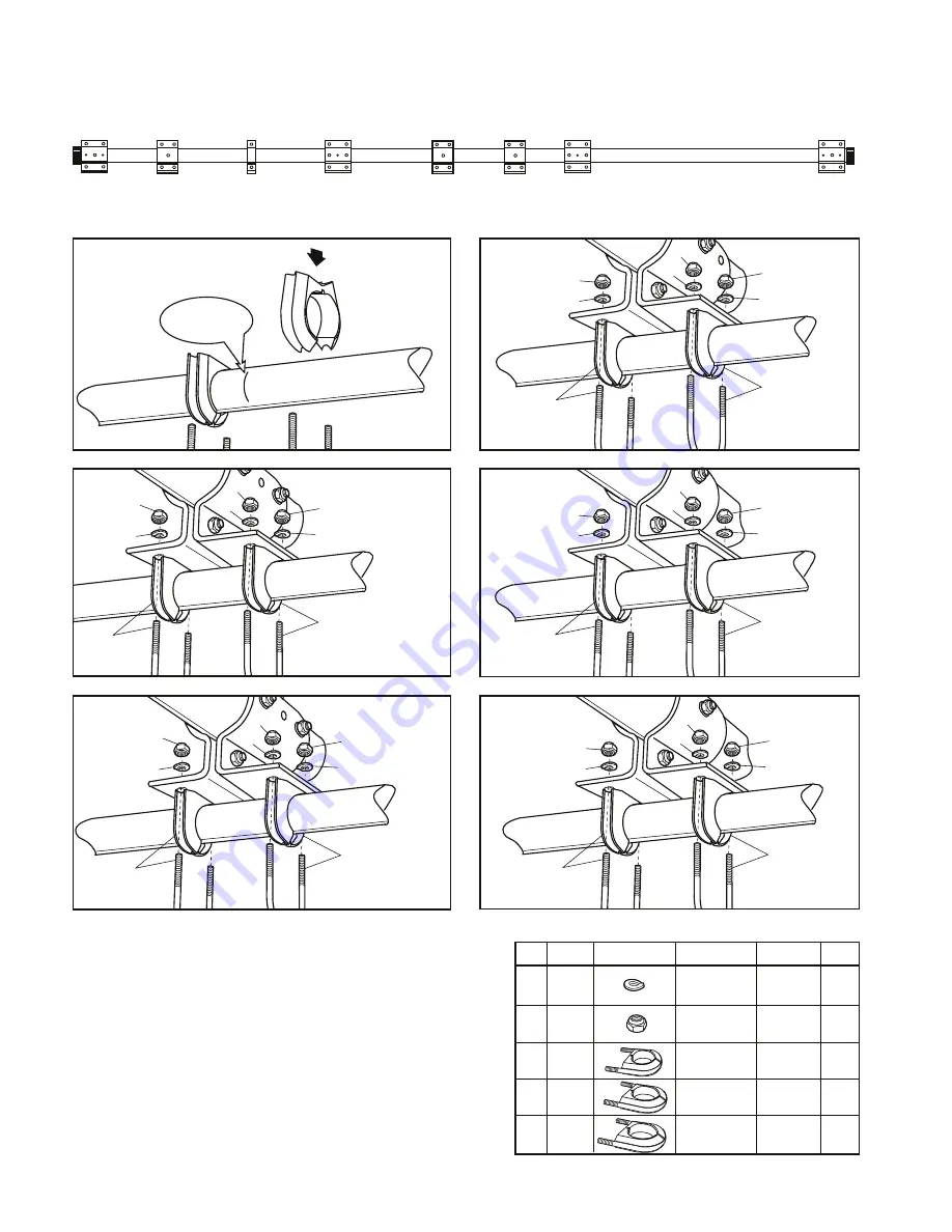
Elements can be attached to the boom when the antenna is on the ground or when
the antenna is being installed on a tower. Identify the hardware required to secure
the elements by using the Element-to-Boom Parts List. Figure 6 shows the position
of each element on the boom. Figures 6A, 6B, 6C, 6D, 6E, 6F show the hardware
required to attach each element to the element bracket Position each element
center mark equidistant between each Cush-A-Clamp. Leave the Cush-A-Clamps
loose on the Log Cell Elements (#3, #4, #5, #6) until the feed straps are attached
in Step 5. There are three sizes of Cush-A-Clamps. Tighten each clamp until the
element tubing can no longer rotate inside the Cush-A-Clamp. The lock washers
under the nuts securing the Cush-A-Clamps should be tightened until they are flat
against the mounting bracket.
495
495
84
99
84
99
84
99
497
497
84
99
84
99
84
99
7/8” Cush-A-Clamp
497
497
84
99
84
84
99
1-1/4” Cush-A-Clamp
99
495
495
84
99
84
84
99
7/8” Cush-A-Clamp
99
496
496
84
99
84
99
84
99
1” Cush-A-Clamp
1-1/4” Cush-A-Clamp
4-Element to Boom Assembly


